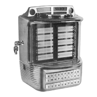
Model 5210
Wall
Box
(3)
When one or more Model 222 Boosters
are used for additional wall box groups, connect the
threewire cable from each wall box group as follows:
Wall Box Terminals No.
1
to Booster
Terminal No.
1
(Pulse)
Wall
Box
Terminals No. 2 to Booster
Terminal No. 2 (Common)
Wall Box Terminals No. 3 to Booster
Terminal No.
3
(24V Power)
NOTE:
The
spade connector
an
the
die
of
the
Model
222
Boosterswill
be
connected to
the
stepper terminal
No.
1
orto
the
No.
1
terminalof
a
previouslyconnect-
ed Model 222
Booster.
In
other
words. all
No.
I
(Pulse)
cables will
be
connected together.
(4)
A
3
Amp. Fustat
is
provided in each
booster for protection of the transformer and the line
to the wall boxes.
h. Line protection for the first group of wall
boxes is provided by a
3
Amp. Fustat located
in
the
stepper and junction box unit.
i.
Test each wall box for proper acceptance of
coins, rejection of slugs, mechanical operation, and
correct selection at the phonograph.
5.
ADJUSTMENTS
a. Slug Rejector.
The slug rejector
is
a product of National
Rejectors,
Inc. of St. Louis, Missouri. Information
may be obtained from any of their branch
offices by
sending for their "Rejector Manual". Adjustments
should
bemade in accordance with their recommenda-
tions.
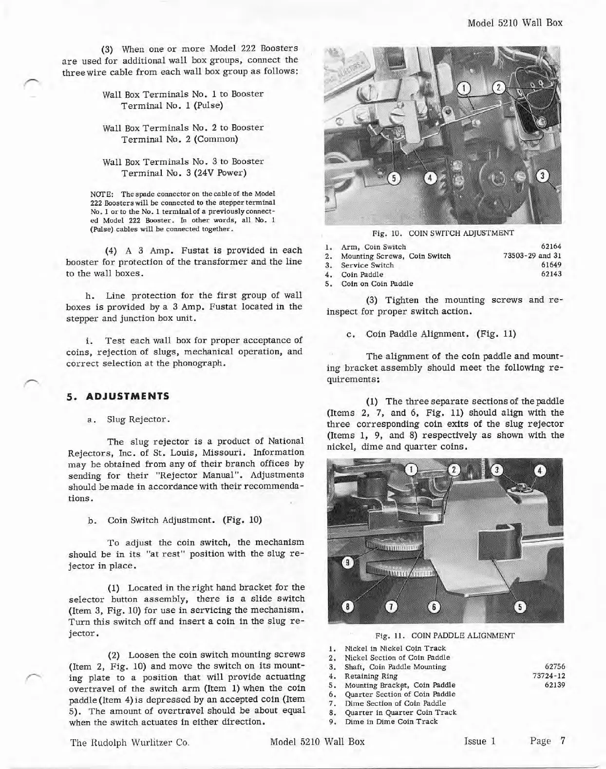
b. Coin Switch Adjustment. (Fig. 10)
To adjust the coin switch, the mechanism
should be in its "at rest" position with the slug re-
jector in place.
(1) Located in
theright hand bracket for the
selector button assembly, there
is
a slide switch
(Item 3, Fig.
10)
for use in servicing the mechanism.
Turn this switch off and insert a coin in the slug re-
jector.
(2) Loosen the coin switch mounting screws
(Item 2, Fig.
10)
and move the switch on
its
mount-
f-*
ing plate to a position that will provide actuating
overtravel of the switch arm (Item 1) when the coin
paddle (Item 4)is depressed by an accepted coin (Item
5).
The amount of overtravel should be about equal
when the switch actuates in either direction.
Fig. 10.
COIN
SWITCH
ADJUSTMENT
1.
Arm,
Coin Switch 62164
2. Mounting Screws, Coin Switch
73503-29
and
31
3. Service Switch 61649
4. Coin Paddle 62143
5. Caln
on
Coin Paddle
(3) Tighten the mounting screws and re-
inspect for proper switch action.
c. Coin Paddle Alignment. (Fig. 11)
The alignment of the coin paddle and mount-
ing bracket assembly should meet the following re-
quirements:
(1) The three separate sections of the paddle
(Items
2,
7,
and
6,
Fig. 11) should align with the
three corresponding coin exits of the slug rejector
(Items
1,
9,
and
8)
respectively as shown with the
nickel, dime and quarter coins.
Fig.
11.
COIN
PADDLE
ALIGNMENl
1.
Nickel in Nickel
C@
Track
2.
Nickel Section
of
Coin Paddle
3. Shaft.
Coin
Paddle Mounting 62756
4.
Reraining
Ring
73724-12
5. Mounting Bracket, Coin Paddle 62139
6.
Quarter Section
of
Coln Paddle
7.
Dime
Section
of
Caln Paddle
8.
Quarter in Quarter Coin,Track
9.
Dime
in
Dime
Coin Track
The
Rudolph Wurlitzer Co. Model 5210
Wall
Box
Issue
1
Page
7


 To Next Page