TRANSMITTER CONNECTORS
mic
inst
XDT4: 1/8” TRS jack plug, unbalanced
8
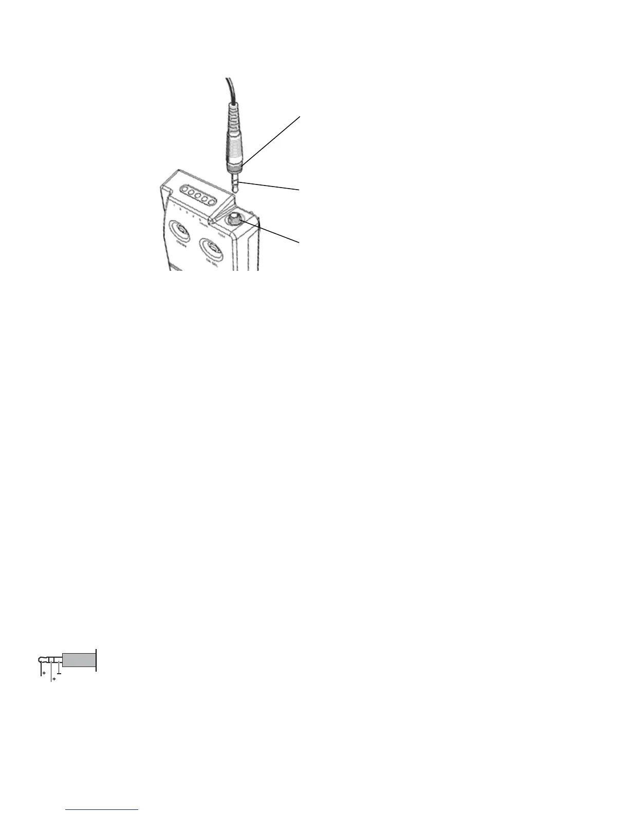
FIGURE 11
Jack Plug -
Insert into jack socket.
Cable polarity: ring (+ instrument), sleeve (-), tip (+ mic)
Input
Threaded input jack socket
Threaded Sleeve -
Secure the 1/8” jack plug in
place by screwing down the
threaded sleeve onto the
socket threads approximately
two turns.
Threaded Sleeve
Secure the 1/8” jack plug in place by screwing down the threaded sleeve onto the input jack socket threads and turn approxi-
mately two times.
Jack Plug
For correct operation, the jack plug must be inserted all the way into the jack socket with the threaded sleeve securely fastened
to the threaded input jack socket.
Threaded Input Jack Socket
Make certain that a secure connection is made for trouble-free operation.
Instrument Input
The instrument input circuit is wired to the ring of the input jack plug and socket.
NOTE: When using anything other than an X2 instrument cable, make certain to ground the tip when using this input
NOTE: Input impedance is 1.3 MΩ
Microphone Input
The microphone input circuit is wired to the tip of the input jack plug and socket
NOTE: When using any other microphone not supplied by X2, make certain to ground the ring when using this input
NOTE: Input impedance is 10KΩ
NOTE: ~9V DC is supplied at the tip