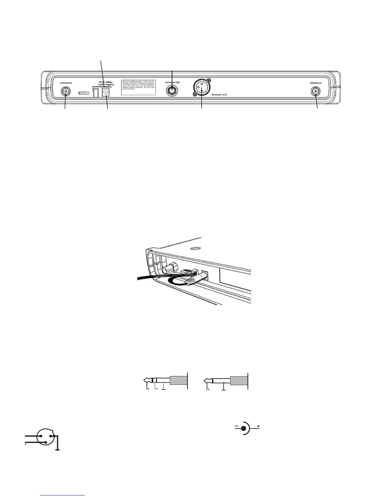
RECEIVER BACK PANEL AND CONNECTIONS
Antenna A & B Input Connector (BNC)
Diversity antenna inputs A and B. For maximum performance range, connect the supplied 1/2 wave antenna by pressing on the
BNC connector and twisting clockwise for ~1/2 turn. NOTE: Antenna inputs ARE NOT DC biased.
Cable Grip
Thread the power supply cable into the CABLE GRIP to secure the connection as shown in figure 5.
DC Power Input
DC socket for connection of power supply, 9V DC 500 mA (supplied).
Power supply Cable Grip
Instrument Out
output 1/4” TRS jack - unbalanced, 1.8kΩ
Balanced Low Z
output XLR(F) - 600Ω
Antenna B
input connector (BNC)
DC Power
input connector (9V DC 500mA)
Antenna A
input connector (BNC)
2 1
3
+
inst
or
inst full
XDR4: DC connector for power supply
4
FIGURE 4
FIGURE 5
Instrument Out
This 1/4” unbalanced TRS output jack (1.8 kΩ) is voiced at the tip for instrument applications (gentle high-frequency role off at 8
kHz approximates sound of a 15’ cable), and full bandwidth (10 Hz to 20 kHz) on the ring. Great for ‘tuner’ out or dual amp
setups.
Balanced Low Z
Balanced XLR, 600Ω, full-bandwidth output (10 Hz to 20 kHz).