©2000 Xantrex Technology Inc.
Installing the DVM/C40
To install the faceplate LCD:
· Disconnect all power sources and remove the factory-installed
faceplate by removing the four Phillips-head screws.
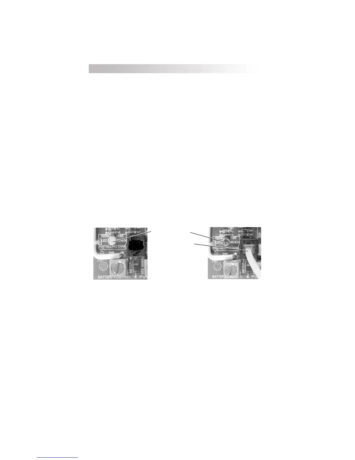
· Pull out the LED indicator near the bottom left corner of the controllers
printed circuit board (PCB) just above the BATTERY POSITIVE +
connector.
· Plug the yellow cable on the CM display into the six-conductor modular
RJ15 connector adjacent to the LED that you just removed.
· Align the faceplate and reinstall the screws.
If the LED must be replaced in the future, it will operate in either orientation,
except if replaced incorrectly, the color of the status LED will be reversed.
The connecting cable for the display is a six-conductor telephone cable with
modular type connectors (RJ15). Although any telephone-type cable will work,
the cables provided with the displays use stranded and tin plated wire for better
performance and longer life.
4.0 OPTIONS
36
Figure 27
Remove LED and Install Cable
Remove LED (pull out)
Install Yellow DVM/C40
Cable
 Loading...