Unpacking and Installation, TWTA Octagon CPU
MNC-0300-003 11 of 22 Revision N
Figure 4, Connector J2 Pinout for EIK Unit
Some amplifiers may have an MS connector. Refer to Figure 5 ,
MS Connector J2 Pinout.
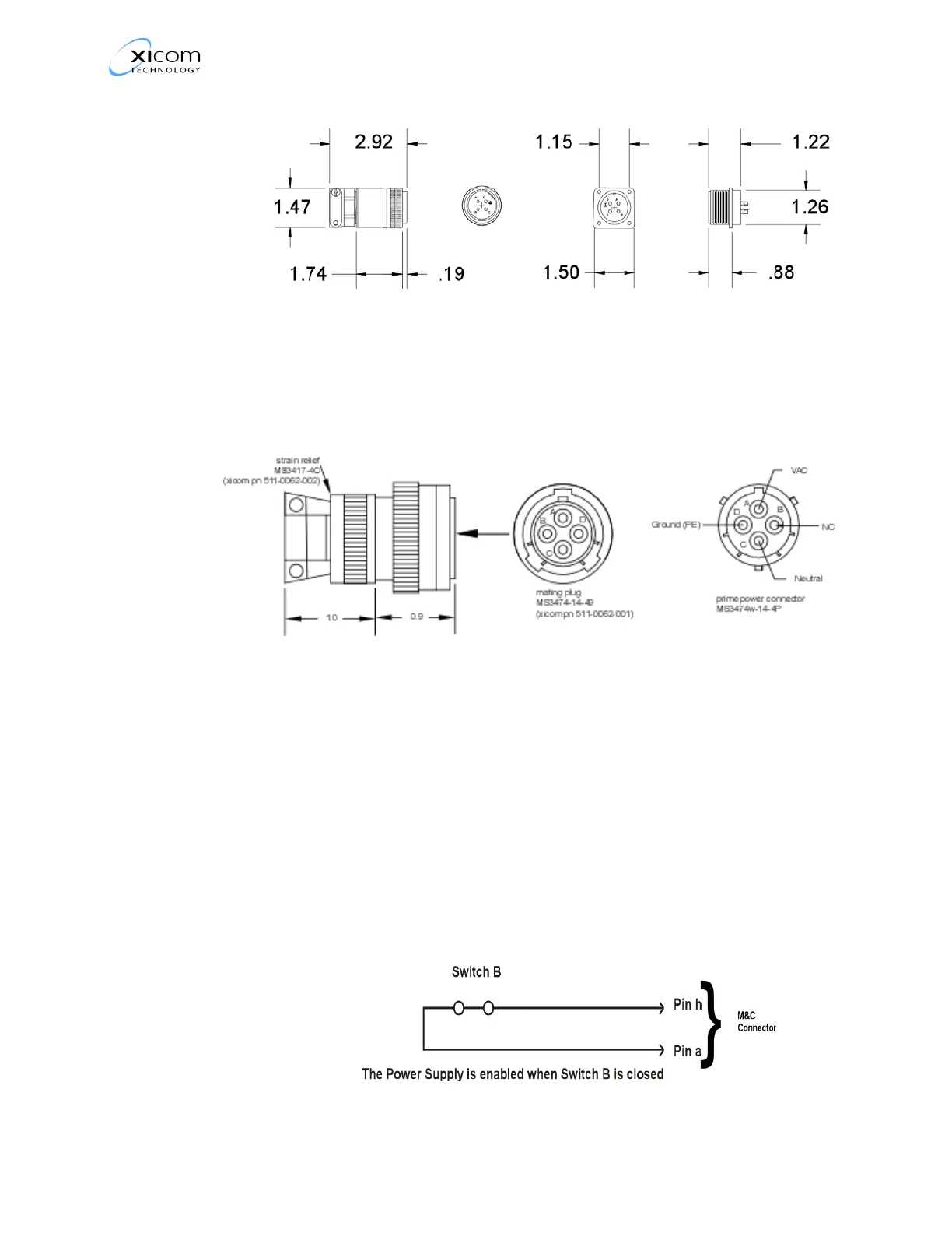
Figure 5, MS Connector J2 Pinout
Refer to the Outline Drawing in the appendix titled Mechanical
Drawings.
External Interlock (Prime power enable)
To enable heater voltage, high voltage and monitor and control
functions pin h (M&C connector) must be connected to ground
(Pins Z or a).
Refer to Figure 6 “, Prime Power Enable Circuit” on page 11 for
pinouts of the Prime Power Enable circuit.
Figure 6, Prime Power Enable Circuit
 Loading...