Unpacking and Installation, TWTA Octagon CPU
MNC-0300-003 12 of 22 Revision N
Monitor and Control Connector
To externally control the amplifier a M&C interface is provided.
The connector is a 32-pin MIL style waterproof connector.
The Monitor and Control connector provides these interfaces for
the use of the customer:
• COM1 — RS-232 Serial Port.
• COM2 — RS-422/ RS-485 Serial Port.
• Two sets of Form “C” Relay contacts for Summary Fault indication.
• External Interlock
• RF Inhibit Control
• 24 VDC @ 100 mA maximum
• 15 VDC for monitoring purposes only.
• Hardware Address Select.
• Discrete High Voltage ON Indicator.
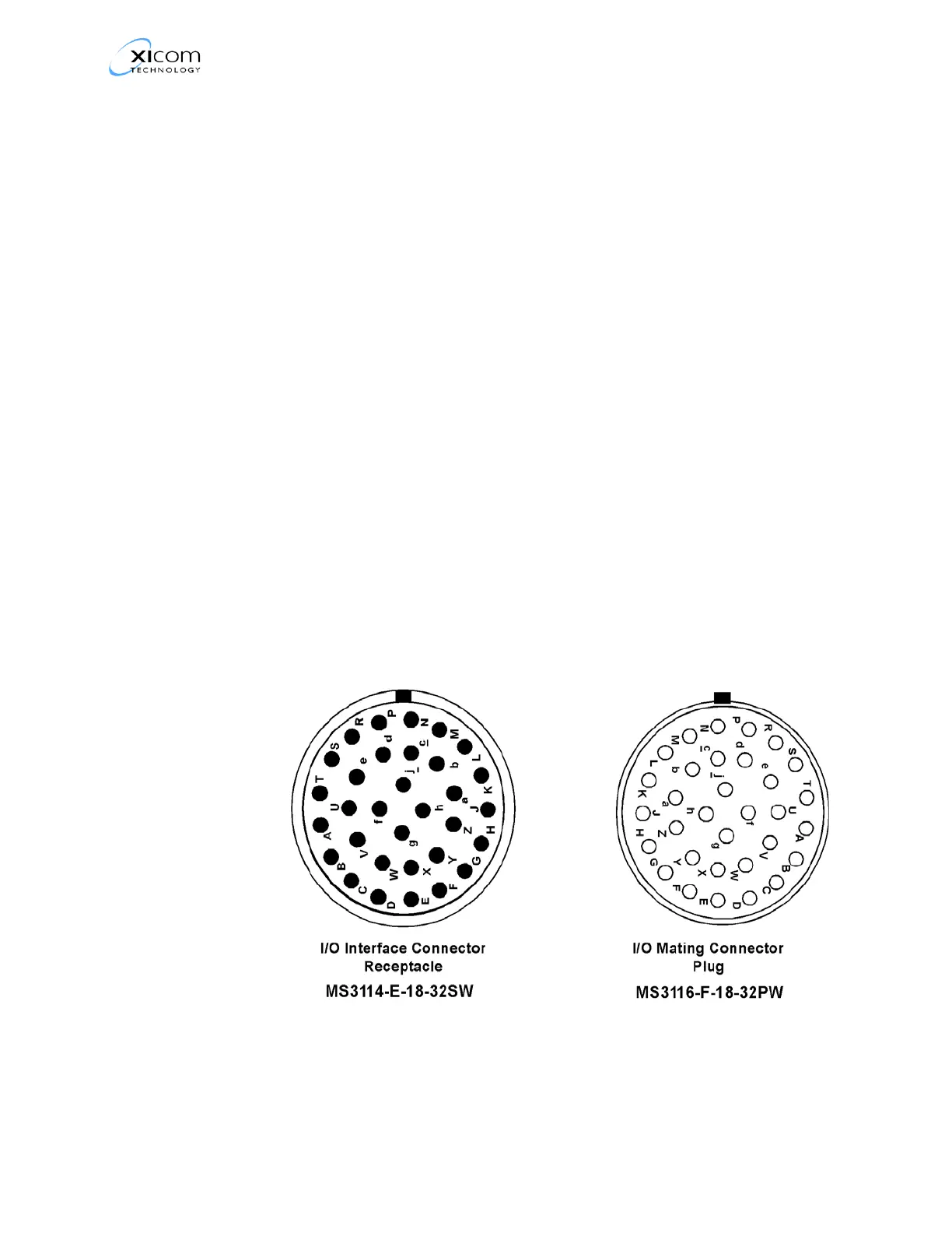
Monitor and Control Pinouts
Figure 7 , M&C Connector Pin Layout shows the pin layout and
Table 2 on page 13, lists the pinouts for the typical Monitor and
Control Connector on the Antenna-Mount Power Amplifier.
Figure 7, M&C Connector Pin Layout
 Loading...