Unpacking and Installation, TWTA Octagon CPU
MNC-0300-003 15 of 22 Revision N
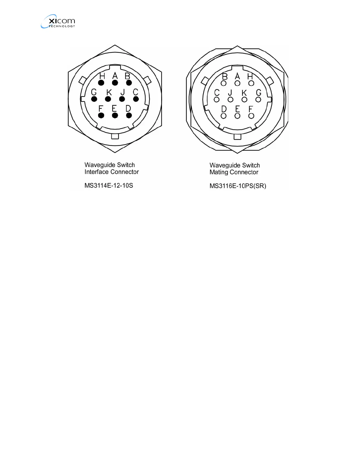
Figure 8, Waveguide Switch Connector Pinouts
RF Inhibit Control (J1-Y)
The TWTA has the capability to Inhibit RF. If the unit has a SSA
preamplifier, inhibit is accomplished by turning off the SSA. If
the unit does not have a SSA preamplifier, the RF Inhibit
command is factory set to disable high voltage to the tube.
Figure 9 , RF Inhibit with Internal Source shows the RF Inhibit
circuit using the TWTA internal 15 VDC and ground. RF will be
inhibited when switch A is closed. When used with a system
controller, pin g can be driven from an external voltage source of
+5 to +15 VDC. In this case pin Y should be connected to the
ground reference of the external supply to prevent damage to
the TWTA or the external supply as shown in Figure 10 , RF
Inhibit with External Source.
 Loading...