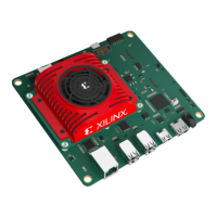
Table 2: Descriptions and Locations
Location Name Description
SOM DS34 PS done LED Lit indicates that the PS has successfully loaded a PL design.
SOM DS35 Heartbeat LED Periodic flashing green LED driven by the Zynq UltraScale+ MPSoC
APU processor.
SOM DS36 PS status LED Status LED, when lit indicates a successful application load.
CC DS1-DS6 Power status LEDs Indicates various power supply and power domain status. Green LED
indicates good status.
CC J2 Pmod Digilent Pmod 2x6 expansion header
CC J3 JTAG Direct JTAG interface, bypasses the FTDI device.
CC J4 FTDI USB2.0 UART and
JTAG
Integrated JTAG and device UART interface via USB2.0
CC J6 DisplayPort DisplayPort video output
CC J5 HDMI HDMI™ video output
CC J7 IAS0 OnSemi image access system (IAS) camera module interface
supporting four MIPI lanes. Connects to OnSemi AP1302 ISP device
sensor 0 interface.
CC J8 IAS1 OnSemi IAS camera module interface supporting four MIPI lanes.
Connected directly to the Zynq UltraScale+ MPSoC HPA bank.
CC J9 RPi camera Raspberry Pi camera module interface. 15-pin variant supporting two
MIPI lanes directly connected directly to the Zynq UltraScale+ MPSoC
HPA bank.
CC J10 Ethernet RJ45 jack 1 Gb/s Ethernet interface
CC J11 microSD card microSD card boot device
CC J12 12V power input 12V power input jack
CC J13 Fan power 12V SOM fan power interface
CC SW1 Firmware update button Push button used during the boot firmware update process.
CC SW2 Reset button Push button that resets the SOM via the device POR_B signal.
CC U44 USB0 Two USB3.0 or USB2.0 compatible connectors
CC U46 USB1 Two USB3.0 or USB2.0 compatible connectors
Chapter 1: Summary
UG1089 (v1.2) July 26, 2022 www.xilinx.com
KV260 Starter Kit 8
 Loading...