HSDP Connector
The HSDP target implements a UFP (upstream facing port) peripheral interface through a USB-C
receptacle connector. The receptacle features four power and four ground pins, two dierenal
pairs for high-speed USB data (though they are connected together on devices), four shielded
dierenal pairs for Enhanced SuperSpeed data (two transmit and two receive pairs), two
Sideband Use (SBU) pins, and two Conguraon Channel (CC) pins.
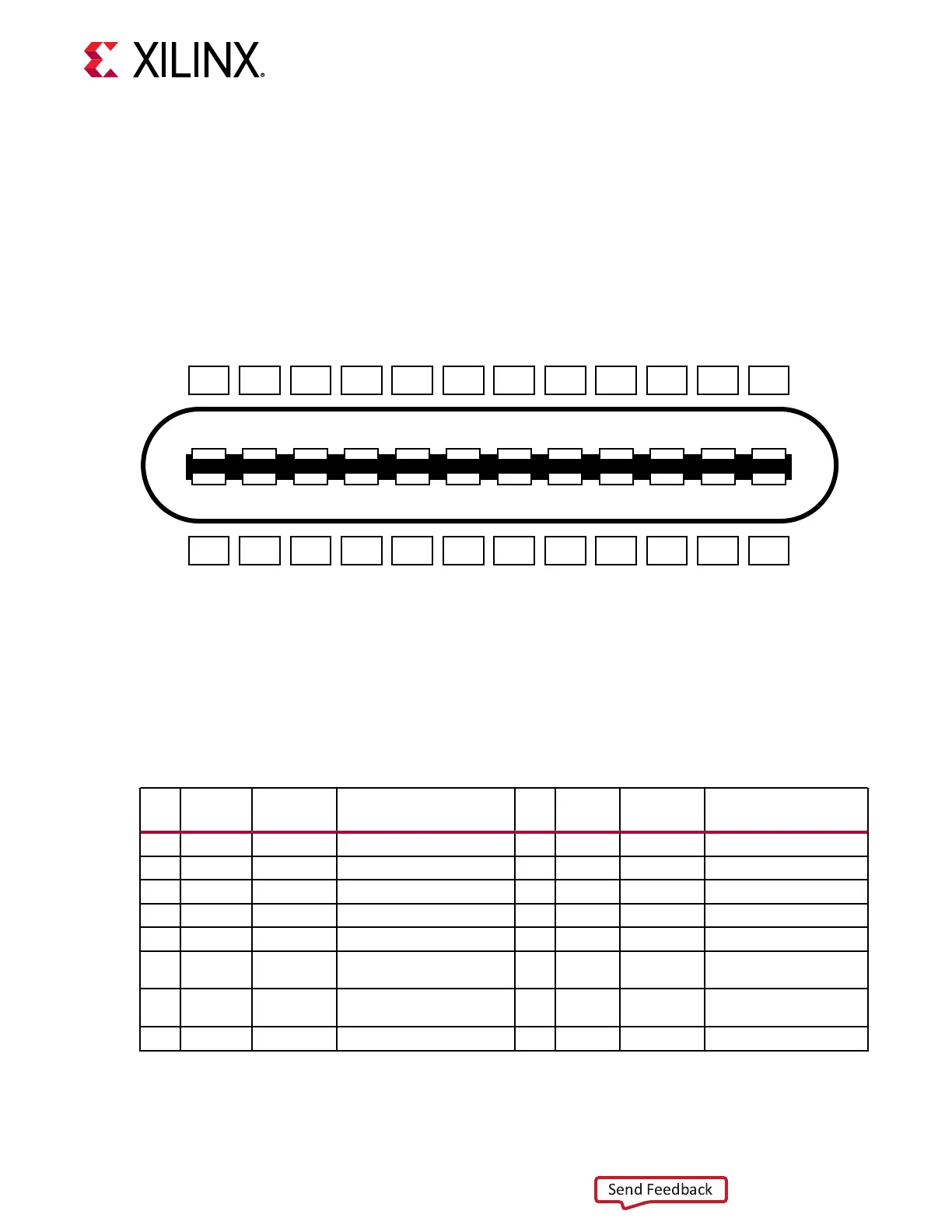
Figure 14: HSDP Connector
GND
A1
TX1+
A2
TX1-
A3
VBUS
A4
CC1
A5
0+
A6
0-
A7
SBU1
A8
VBUS
A9
RX2-
A10
RX2+
A11
GND
A12
GND RX1+ RX1- VBUS SBU2 0- 0+ CC2 VBUS TX2- TX2+ GND
B12 B11 B10 B9 B8 B7 B6 B5 B4 B3 B2 B1
X25132-022221
Note: The SmartLynq+ Module high-speed serial interface does not support USB-C compliant devices;
however, USB-C compliant devices will not be damaged if they are accidentally plugged into this interface.
Pin assignments are idened in the following table.
Table 7: HSDP to USB-C Connector Pin Assignments
Pin
USB
Name
HSDP
Name
Description Pin
USB
Name
HSDP
Name
Description
A1 GND GND Ground return B12 GND GND Ground return
A2 SSTXp1 HSDP-TXp HSDP diff pair, TX, positive B11 SSRXp1 HSDP-RXp HSDP diff pair, RX
A3 SSTXn1 HSDP-TXn HSDP diff pair, TX, negative B10 SSRXn1 HSDP-RXn HSDP diff pair, RX
A4 Vbus Vbus Bus power (from host) B9 Vbus Vbus Bus power (from host)
A5 CC1 CC1 Configuration channel B8 SBU2 SBU2 Sideband use (SBU)
A6 Dp1 Dp1 USB 2.0 differential pair,
position 1, positive
B7 Dn2 Dn2 USB 2.0 differential pair
A7 Dn1 Dn1 USB 2.0 differential pair,
position 1, negative
B6 Dp2 Dp2 USB 2.0 differential pair
A8 SBU1 SBU1 Sideband use (SBU) B5 CC2 CC2 Configuration channel
Chapter 9: HSDP Target Interface
UG1514 (v1.0) March 8, 2021 www.xilinx.com
SmartLynq Module+ 31