Spartan-6 FPGA GTP Transceiver SIS Kit (HyperLynx) www.xilinx.com 15
UG396 (v1.0) June 10, 2010
Getting Started
3. Add a checkmark to all nodes to plot.
4. Select the type of stimulus for HyperLynx to generate. The oscilloscope has several
stimulus waveform options available:
a. The Standard radio button under the Operation section provides options to run a
single rising or falling edge simulation or a pulse train of a certain frequency and
duty cycle.
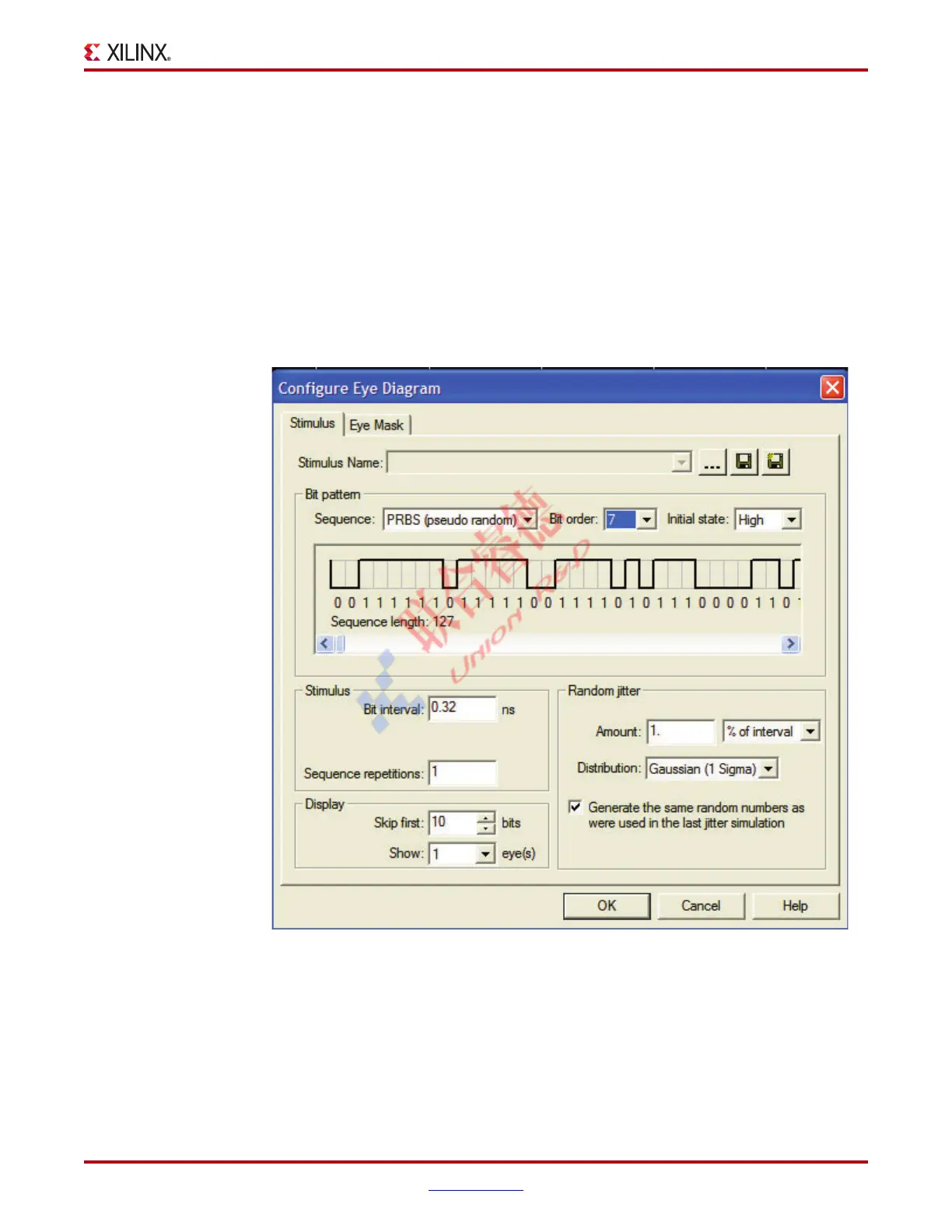
b. The Eye Diagram radio button under the Operation section provides capabilities
to set up various bit sequences after the Configure button is clicked. The available
Bit Pattern selection includes PRBS, 8B/10B, Toggling, USB 2.0, and Custom
patterns (see Figure 1-7). The Configure Eye Diagram dialog box also allows the
user to set up an eye mask for the eye diagram display in the oscilloscope. Refer to
the HyperLynx manuals for more details on how to set up these parameters.
Notes relevant to this section:
• The frequency of the pulse train and the time of the bit interval specified in the
oscilloscope must match the data rate setting in the TX configurator. Each setting has
to be done explicitly.
X-Ref Target - Figure 1-7
Figure 1-7: 3.125 Gb/s PRBS 7 Stimulus

 Loading...