193
P-
P+5V
P+24V
D-
D+5V
D+24V
SI1
SI2
SI3
SI4
+24V
SO1
SO2
COM
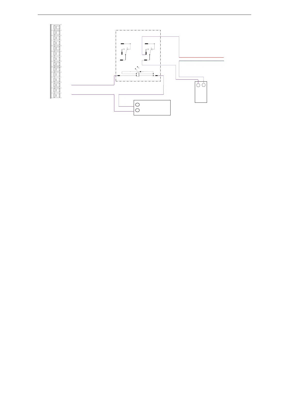
1. P5-44 defines the terminal of the brake output signal. As shown in the figure above, the SO1 controls
brake, that is, P5-44 = 0001.
2. Extend the delay time of servo OFF P5-07 (default 500ms), and the waiting time of braking
instruction P5-09 is set to 0, which can be responded.
Q7: The initial direction is not what I want. How can I change it through a servo driver?
Change the initial direction by modifying P0-05, set the value to 0 or 1, and take effect after
re-energizing. (For mode 2, 4, 6, 7 only). If the internal speed mode (mode 3) is used, the positive and
negative values of the speed setting can be changed.
Q8: How do the two modes switch to each other?
Both P0-01 main mode and P0-02 sub-mode set the required mode. P5-30=0002 and SI2 are defined as
mode switching terminals. When the SI2 terminal has no signal, it runs according to the set mode in the
main mode P0-01. When the SI2 terminal has signal input, it runs according to the set mode in the
sub-mode P0-02.
Note: SI2 terminal signal can be switched only if it is a constant ON signal.
Q9: What is the connection mode between PLC and servo?
1. NPN low-level output PLC: Y0 pulse connects P-, Y1 direction connects D-, +24V connects P+24,
D+24. (Xinje PLC as an example)
PNP high-level output PLC: Q0.0 pulse connects P+24, Q0.2 direction connects D+24, 0V connects P-,
D-. (Siemens PLC as an example) as follows:
9
5
1
12
8
4
13
14
OMRON
MY2NJ
24VDC
 Loading...
