36
3.2 Classification and function of signal terminals
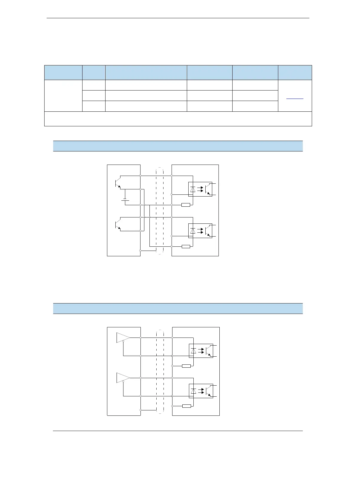
3.2.1 Pulse signal
Open collector (24V voltage) input signal is P+ (pin 3) / D+ (pin 6)
Input signal of differential mode (5V voltage) is P+ (pin 2) / D+ (pin 5)
The wiring diagram of P + D, CW, CCW and AB phase interface circuit is as follows:
Open collector (24V voltage)
PLC, CNC and SCM servo driver
Note:
(1) The supply voltage range of P-/P+24V and D-/D+24V is 18V~25V. If it is below 18V, there
may be pulse and direction anomalies.
(2) In order to resist interference, twisted-pair shielding wire must be used.
Differential mode (5V voltage)
PLC, CNC and SCM servo driver
Note: In order to resist interference, twisted-pair shielding wire must be used.
When the upper
device adopts
collector open
circuit output,
use this
connection
method, please
pay attention to
suspending P+
5V and D+ 5V.
When the upper
device uses 5V
differential
signal output,
the graphic
connection
method is
adopted, please
pay attention to
suspending P+
24V and D+
24V.
 Loading...
