Do you have a question about the Xomax XM-VRSU727BT and is the answer not in the manual?
To avoid accidents, do not handle the unit while driving. Stop and park the vehicle safely.
Use only 12 Volt on-board power supply with proper grounding. Incorrect configuration risks fire.
Do not block vent holes. Ensure vehicle interior temperature is below +60°C. Do not operate if too hot.
Do not open or repair the unit yourself. Contact professionals for any technical problems.
Set loudness appropriately to hear external noises. High loudness can damage hearing.
When replacing fuses, ensure the new fuse has the same amperage as the old one.
Keep the unit clean. Use a soft, dry cloth for dust. Use a damp cloth for soilings, avoid chemicals.
Do not press too hard. Use finger or stylus. Avoid sharp articles to prevent damage.
Avoid moist environments to prevent fire or electric shock.
Read advice carefully before installation. Improper installation voids warranty. Professional installation is recommended.
Disconnect the vehicle battery before installation to avoid short circuits. Refer to the vehicle manual.
This unit is SingleDIN size. Ensure your vehicle has a compatible installation cell. Faceplates/adapters may be needed.
Do not cut or short-circuit connection cables. Doing so voids the warranty.
Connect minus (-) to ground. Ensure clean ground. Tag speaker polarity and connect negative speaker cables to ISO sockets.
Ensure colored cables match the wiring diagram. Ensure cables have the same purpose when connecting other devices.
Speakers should have 4-8 Ohm impedance and sufficient wattage. Ensure speakers are intact to avoid unit damage.
Lay and fix cables tidily. Ensure cables do not contact movable or hot objects.
Connect red cable to ignition switch if no ACC. Avoid routing yellow cable through engine bay.
Do not connect speaker cables to each other. Isolate unused cable endings. Never connect negative speaker cables to the vehicle body.
For optimal performance, the integration angle should be +/- 30 degrees.
This manual is generalized. Product specific discrepancies may occur, especially with depictions of accessories.
Find the detailed manual for your XOMAX product on our homepage: www.xomax.de/download.
Overview of installation steps, including fixture accessories, installation frame, dual-ended bolt, unit, bezel, and front panel.
Fix the metal sheet in the vehicle. Pull the dual-ended bolt through a hole. Unit is fixed later with washer and nut.
Remove installation frame from unit using extraction keys. Insert frame into car radio slot and bend cogs to secure.
Connect the ISO cable to the unit and vehicle. Connect the radio aerial. Slide unit into the frame until it clicks.
Pull the dual-ended bolt through the fixation metal sheet and secure with washer and nut.
You will need a spanner (wrench) for the fixation nut and extraction keys (optional) to release the unit.
Unloose the fixation nut on the rear of the unit using a spanner. This step may be skipped if the unit was not fixated.
Insert extraction keys into recesses between the installation frame and unit housing, ensuring they are centered.
With keys inserted, press holding side-cogs outwards to release the unit from the frame. Carefully pull out the unit.
Pull the unit carefully out of the frame or slot. Disconnect all cables, including the ISO multicore.
Finally, remove all installation accessories such as the fixation metal sheet and installation frame.
Diagram showing connections for radio aerial, video input, audio input, video output, external displays, rear camera, and loud speakers.
Diagram illustrating connections for radio aerial, phantom power, permanent current, ignition, and loud speakers via ISO plug.
Details for socket A pins: A1-A3 spare, A4 (+12V steady), A5 (antenna), A7 (+12V ignition), A8 (ground).
Details for socket B pins: B1/B2 (rear right), B3/B4 (front right), B5/B6 (front left), B7/B8 (rear left) with polarity.
Warning about potential ISO plug pin assignment variations. Mismatches can cause errors. Consult manuals if needed.
Connect brown (KEY 1), white/orange (KEY 2), and black (ground) for steering wheel remote control functions.
Connect pink for rear view camera trigger and green for hand brake (ground).
Explains the terminal plug and ISO plug function as an extension cable for vehicle connection with standardized ISO plugs.
It is recommended to let a professional technician install the unit.
Check battery film, battery level, and ensure IR receiver is not blocked. Test with a camera.
Likely due to wrong ISO cable connection. Review ignition and steady plus pin assignments.
Note on ISO plug standardization and potential pin assignment variations leading to errors.
Identify antenna type (passive, active, diversity) for troubleshooting poor radio reception. Solutions depend on antenna type.
Caused by wrong ISO cable connection. Interchange ignition plus and steady plus cables. Check fuses if applicable.
Dispose of electric/electronic devices at municipal collection points. Proper disposal contributes to environment protection.
Dispose of empty batteries at municipal collection points. Batteries with pollutants are labeled.
This document provides the installation and safety instructions for the XOMAX XM-VRSU727BT car multimedia system. It covers essential information for safe operation, proper installation, and basic troubleshooting.
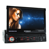
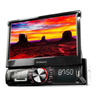
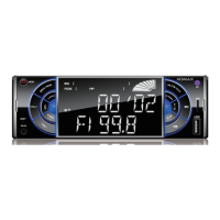
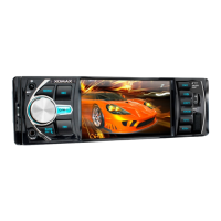
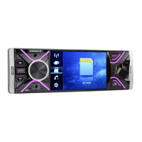
The XOMAX XM-VRSU727BT is a car multimedia system designed to provide audio and video entertainment, as well as connectivity features within a vehicle. It supports various input sources and offers outputs for external displays and amplified sound systems. The unit is equipped with a touchscreen interface for user interaction and can be controlled via a remote control. It integrates with the vehicle's electrical system, including the radio aerial, and supports connections for rear-view cameras and steering wheel remote controls.
| Brand | Xomax |
|---|---|
| Model | XM-VRSU727BT |
| Category | Car Video System |
| Language | English |