Do you have a question about the Xtant M Series and is the answer not in the manual?
Importance of retaining the sales receipt for warranty claims and future reference.
Emphasizes the necessity of adhering to all usage and installation instructions for proper operation.
Details minimum wire gauge requirements for power, ground, remote turn-on, and speaker cables.
Specifies the need for outboard fuses for M Series amplifiers for safety and protection.
Advises against installing amplifiers in locations exposed to moisture or water.
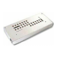
Lists the key features and capabilities of the Xtant 121M amplifier model.
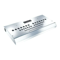
Outlines the standard features and technical specifications for the Xtant 202M amplifier.
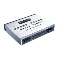
Details the standard features and operational aspects of the Xtant 404M amplifier.
Guidelines and considerations for securely mounting the amplifier in a vehicle for optimal performance and cooling.
Instructions for connecting the power and ground cables correctly and safely to the amplifier.
How to connect the remote turn-on wire to power the amplifier on and off with the source unit.
Procedures for correctly connecting speaker wires to the amplifier for proper audio output.
Explanation of how to bridge amplifier channels for higher power mono output and system flexibility.
Information on connecting audio sources via RCA inputs and routing cables.
Guide to utilizing the Balanced Line circuitry for improved audio quality and noise reduction.
Instructions on how to adjust the amplifier's output gain for optimal volume and sound quality.
Details the PQM-1 module for precise frequency, Q, and gain adjustments in tuning.
Describes the LFQ 45 module for adding selectable bass boost levels to the audio system.
Information on the CM 24x module, a 24 dB/octave crossover for improved speaker response.
Explains the CM 12H (High-Pass) and CM 12L (Low-Pass) modules for frequency filtering.
A compatibility list for various Xtant accessory modules and their mounting orientations.
Explains the jumper settings to activate or bypass the 121M's built-in low pass crossover.
How to use the service jumper to turn the amplifier on/off for adjustments or diagnostics.
Details the specific positions of the service jumper and their functions.
Explains the meaning of the Red, Yellow, and Orange diagnostic LEDs on the amplifier.
Outlines the company's commitment to customer satisfaction and efficient service procedures.