VESDA-EVEP-A00-P Product Guide
www.xtralis.com 39
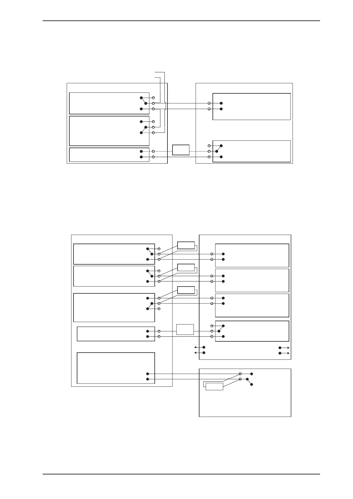
4.3.9 Typical Wiring to Fire Alarm Control Panel (FACP)
The diagram below shows the correct way to wire VESDA-E detectors to a conventional fire alarm control
panel (FACP).
Normally Closed (NC)
CommonFIRE 1 (C)
(NO)Normally Open
Normally Closed (NC)
Common (C)URGENT FAULT
(NO)Normally Open
Unmonitored GPI
( “R ”)Set to eset
Dete torc
(NC)
(C)
(NO)
Input
EOL = Normal
Short = Fire
Open = Fault
To next detector
or End of Line resistor (EOL)
Fire Panel (FACP)
+
-
+
-
5-30VDC
The relay is
energised on reset.
Relay shown energized which
is the no-fault condition
Figure4-37: Typical wiring to a fire panel with EOL
4.3.10 Typical Wiring to Addressable Loop Module
This wiring example is for wiring VESDA-E detectors to a typical third party Input/Output Loop module 3
inputs 1 output.
Note: These are example drawings. Refer to the appropriate product manual for the exact wiring details of
the third party equipment.
Normally Closed (NC)
Normally Open (NO)
Normally Open (NO)
Normally Closed (NC)
Normally Open (NO)
Fire Input
EOL* = Normal
Short = Fire
Open = Wiring Fault
EOL* = Normal
Short = Fire
Fault Input
EOL* = Normal
EOL*
EOL*
EOL*
(NC)
(NO)
Monitored GPI
(Set to ”Mains OK”)
PSU
+
-
+
-
5-30VDC
(NC)
(NO)
This shows normal operation (no fault).
EOL*
Relay shown energized which
is the no-fault condition
EOL* = Normal
Open = Wiring Fault
3 Inputs 1 Output Loop Module
*EOL: End of Line Resistor
To next detector
Unmonitored GPI
(Set to “Reset”)
Detector
Fire 1 Common (C)
Normally Closed (NC)
Action Common (C)
Fault Common (C)
Short = PSU Fault
Pre Alarm
Open = Wiring Fault
Short = Detector Fault
Open = Wiring Fault
(C)
The relay is
energised
on reset
To FACP
(C)
The power supply’s fault reporting
relay is energized.
Figure4-38: Input/Output Loop Module with EOL
4.3.11 Typical Wiring for Monitored GPI for PSU Monitoring
The diagram below shows the correct way to configure power supply monitoring. It also shows where an End
Of Line (EOL) resistor is correctly installed. Refer to Section 4.3.8 on page 38 for further information.