B
Barbara Rose DDSAug 3, 2025
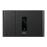
What does a power fault mean on my Xtrails VESDA VLI Smoke Alarm?
- CchristinalopezAug 3, 2025
If the monitored GPI Function is used, a lit LED indicating a power fault on your Xtrails Smoke Alarm signals a fault in the power supply.