VESDA by Xtralis VESDA VLI Product Guide
www.xtralis.com 43
5.5.4 Input / Output Options
Input / Output options provide the ability to control the behavior of the General GPI and latching behavior of the
fault and alarm relays.
The unmonitored GPI can be configured to initiate a number of different actions - including, by default, a
Remote Reset function.
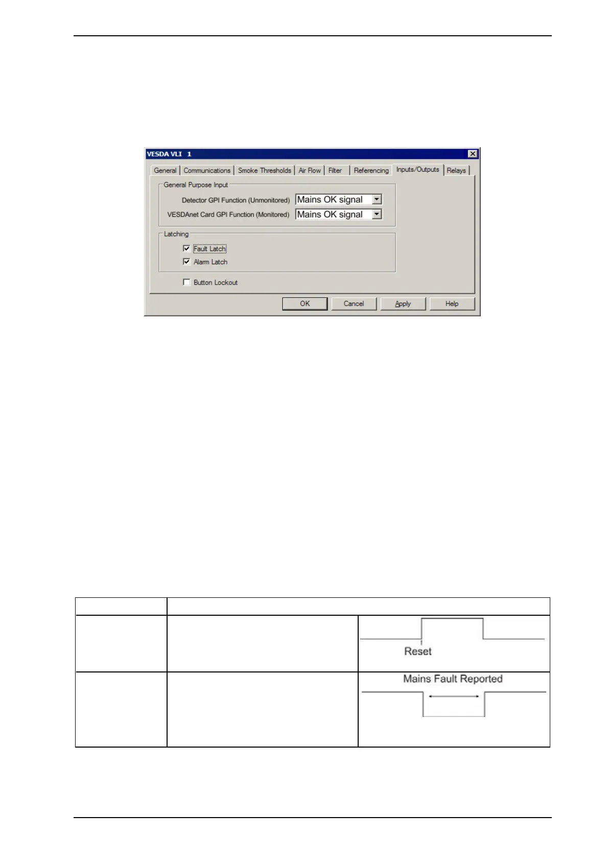
Figure 5-14: Input / Output Options
The Input / Output configuration options are as follows:
General Purpose Input (GPI)
The GPI is a remote input device for the detector that can be programmed to perform one of several functions.
Refer to Table 5-3 below for a description of the individual selections.
l Detector GPI Function (Unmonitored): Supported by VLI-880 and VLI-885.
l VESDAnet Card GPI Function (Monitored): Supported by VLI-885.
Latching
l If Fault is checked, the fault relay is energized during normal operation. This means that should the
detector suffer a power failure, the relay will go to the non-energized fault condition. This is the
recommended setting.
l If Alarm is checked, the alarm relay is energized during normal operation. This means that should the
detector suffer a power failure, the relay will go to the non-energized alarm condition. This is NOT the
recommended setting.
Button Lockout
If checked, the Reset / Disable button on the front of the detector is disabled.
Function State Change
External Reset Detector Reset on a 0 VDC to 5 VDC
rising edge.
Mains OK The detector monitors the state of the
external power supply and responds to the
following conditions.
l Mains OK ≥ 5 VDC at this terminal.
l Mains Fail ≤ 2 VDC at this terminal.
Table 5-3: Unmonitored GPI Operation