VESDA VLF-500-UL 7Ed Product Guide VESDA
10 www.xtralis.com
2.4 Detector Removal
Precaution: Electrostatic discharge precautions need to be taken prior to removing the front cover from the
detector.
Note: Take the necessary steps to advise the monitoring authority of work being carried out and that the
system needs to be disabled.
1. Turn off the power to the detector.
2. Disconnect the sampling pipes.
3. Push in the security tab and lift up the field service access door, refer to Figure 6-3 on page 31 for
further information.
4. Unscrew the front cover retaining screws (E).
5. Lift off and swing down the front cover, a restraining strap will take the load. For inverted mounted
detectors the cover should be removed and placed aside.
6. Disconnect all field wiring from the terminal block.
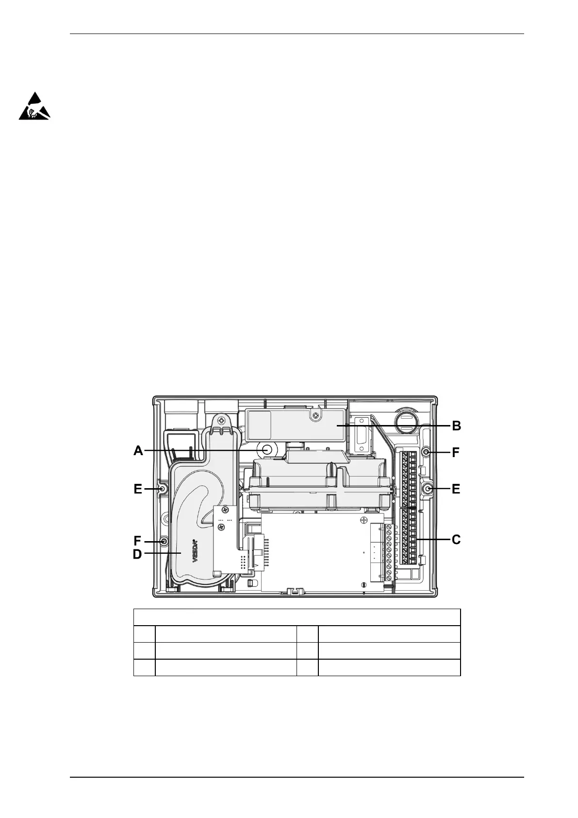
7. Unscrew the two M4 x 20 mm locking screws on the left and right side of the detector. See the items
marked (F) in Figure 2-7 below.
8. Use a screw driver to push down the anti-tamper clip in hole (A), at the same time, push the detector
base up.
9. Lift the detector off the mounting bracket.
Once the detector has been removed re-fit the front cover to keep the internal components safe from damage
and the electrical cabling safe.
Note: For inverted mounted detectors, the front cover will need to be removed prior to unhooking the
detector from the mounting bracket. Disconnect the retaining strap and the ribbon cable from the
user interface card and place the cover aside.
Legend
A Anti-tamper clip access hole D Aspirator
B Air Filter Cartridge E Retaining screw
C Terminal block F Bracket locking screw holes
Figure 2-7: Detector removal
 Loading...