VESDA VESDA VLF-500-UL 7Ed Product Guide
www.xtralis.com 15
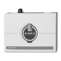
2.7.5 Relays (Terminals 12 - 20)
The relays allow alarm and fault signals to be hard wired to external devices, such as fire alarm control panels
and loop interface modules away from the detector (example, sounding a siren at Action threshold). Refer to
the appropriate installation manual for connectivity instructions.
Legend
12 NC Fault Relay
13 Common
14 NO
15 NC Action Relay
16 Common
17 NO
18 NC Fire 1 Relay
19 Common
20 NO
NC Normally closed
contact of relay (with
no power applied).
NO Normally open contact
of relay (with no power
applied).
Common Common contact for
the relay.
Figure 2-12: Terminal block display, relays
Note: By default, the Fault relay is normally energized when no fault is present. For example when there
is no fault present, terminal 12 is held open and terminal 14 is held closed. When there is a fault
present, terminal 12 is held closed and terminal 14 is held open.
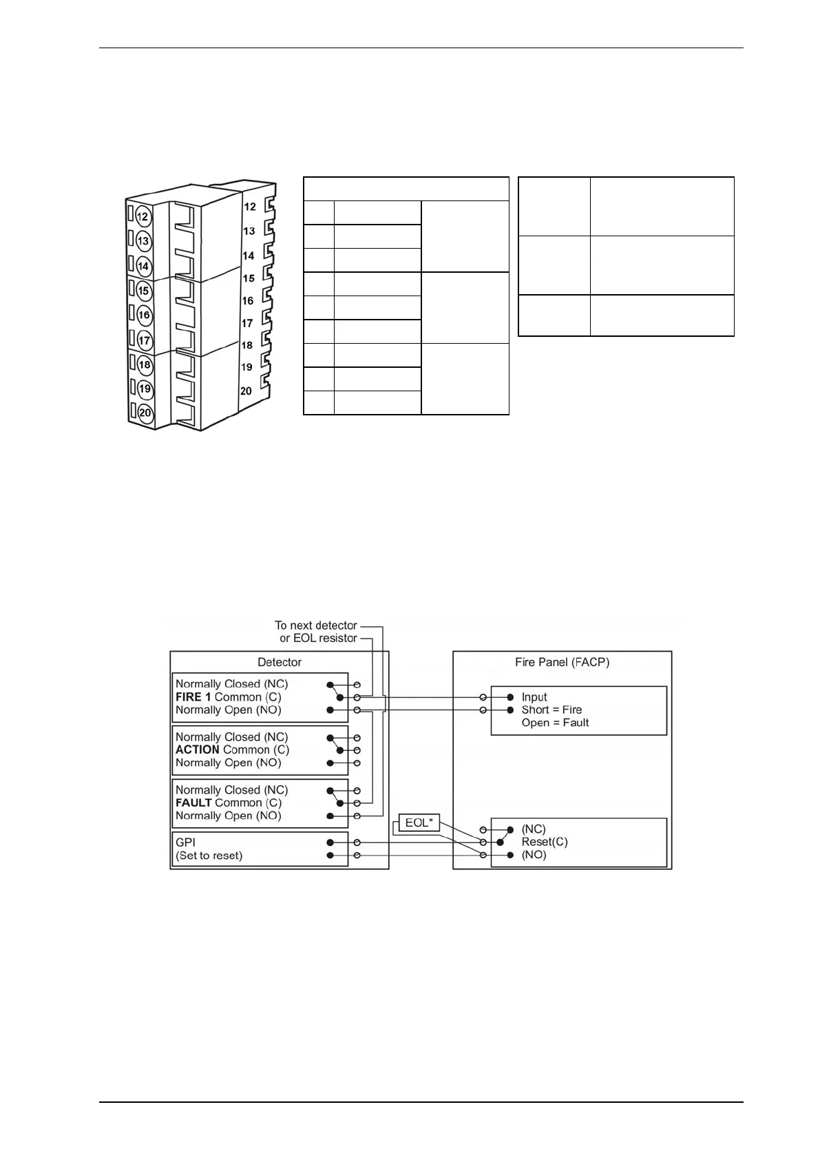
2.7.6 Typical Wiring To Fire Alarm Control Panel (FACP)
The diagram below shows the correct way to wire VESDA detectors to a conventional fire alarm control panel
(FACP). It also shows where an End Of Line (EOL) resistor is correctly installed.
Figure 2-13: Typical wiring to a fire panel with EOL
 Loading...