VESDA by Xtralis VESDA PipeNetwork Design Guide
www.xtralis.com 21
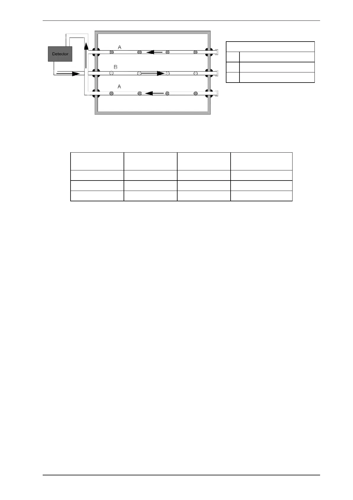
Legend
A Sampling Pipe
B Exhaust Pipe
C Air flow
Figure 4-22: Cross section view of pipe and hole setup for large duct
For large ducts, holes are nominally spaced each 400 mm (16 in).
Duct width No. of holes Hole Ø Nominal pipe flow
rate (L/min.) (cfm)
1 m (3 ft 4 in) 6 3.5 mm (9/64 in) 42.2 L/min. (1.49 cfm)
1.5 m (5 ft) 8 3.0 mm (1/8 in) 41.4 L/min. (1.46 cfm)
2 m (6 ft 6 in) 10 3.0 mm (1/8 in) 50.0 L/min. (1.76 cfm)
Table 4-2: Hole size for large duct
ASPIRE2 calculations shown in Table 4-1 and Table 4-2 apply to a 5 m (16.4 ft) inlet pipe and a 2 m (6.56 ft)
exhaust pipe. Always check with local codes and standards for sampling hole spacing.
4.6.1 Condensation from Ducts
Condensation may occur when the air being sampled is warmer than the air surrounding the detector. Refer to
the VESDA Pipe Network Installation Guide for information on how to avoid condensation problems.