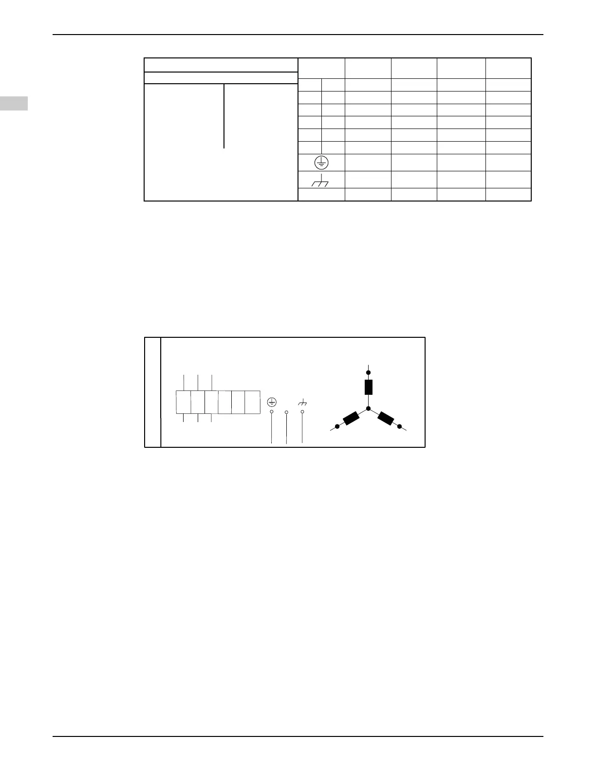
4.2.6.1 Colors and markings of leads
863 17 00 (REV 2)
COLOUR STANDARD
BN=Brown
BK=Black
WH=White
OG=Orange
GN=Green
GN/YE=Green-Yellow
RD=Red
GY=Grey
BU=Blue
YE=Yellow
STATOR LEADS
U1,U5 RD
U2,U6 GN
V1,V5 BN
V2,V6 BU
W1,W5 YE
W2,W6 BK
T1,T2 WH/YE
*SUBCAB AWG
* * Ground Conductor is stranded around cores
GC=Ground Check
Colours and marking of main leads
Motor connection
1 L1 BK 1 BN RD BN
2 L2 BK 2 BK BK BK
3 L3 BK 3 GY WH GY
L1 BK 4
- - -
L2 BK 5
- - -
L3 BK 6
- - -
GN/YE GN/YE GN/YE
**Screen/PE
from cores
Screen (WH) Screen (WH)
-
Screen (WH)
Mains
1~ 3~
SUBCAB 7GX
Screenflex 7GX
SUBCAB 4GX
Screenflex 4GX
SUBCAB AWG
SUBCAB
Screened
GC YE
-
WS004125E
Figure 7: 3–phase and 1–phase without built-in starter
For markings on sensor leads, see
Sensors connection
on page 33.
4.2.6.2 Connections included
•
3-phase connection
on page 28
•
1-phase connection
on page 32
•
Sensors connection
on page 33
•
Screened cable connection
on page 33
4.2.6.3 3-phase connection
3 PHASE
3 Leads
GC
*YE
L1
L2
L3
U1
V1
W1
U1
U1
V1
V1
W1
W1
U2
U2
V2
V2
W2
W2
GN/YE
WH
L3
L2
L1
V1
W1
U1
WS009162B
4 Installation
28 Flygt 3069 Installation, Operation, and Maintenance Manual
EN




 To Next Page