6
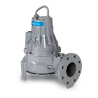
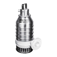
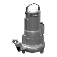
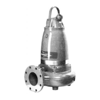
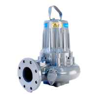
GENERAL DESIGN OF A FLYGT PUMP
Design
The pump is a submersible, electric motor-driven
product.
1. Impeller
The pump is available with a wide range of impellers
for different applications and capacities.
2. Shaft seals
The pump has two mechanical face seals – one inner
and one outer, with an intermediate oil housing.
3. Shaft
The shaft is delivered with the rotor as an integral part.
Shaft material: stainless steel.
4. Bearings
The support bearing of the rotor consists of a single-
row ball bearing.
The main bearing of the rotor consists of a two-row
angular contact ball bearing.
5. Oil housing
The oil lubricates and cools the seals and acts as a
buffer between the pump housing and the electric
motor.
6. Motor
Squirrel-cage 1-phase or 3-phase induction motor for
50 Hz or 60 Hz.
The motor can be started by direct on-line or star-delta
starting.
The motor can be run continuously or intermittently
with a maximum of 30 evenly spaced starts per hour.
Flygt motors are tested in accordance with IEC 34-1.
The stator is insulated in accordance with class H
(180°C, 360°F). The motor is designed to deliver its
rated output at ± 5% variation from the rated voltage.
Without overheating the motor, ± 10% variation from
the rated voltage can be accepted provided that the
motor does not run continuously at full load. The
motor is designed to operate at a voltage imbalance
of up to 2% between the phases.
Monitoring equipment
The stator incorporates thermal contacts connected in
series.
The pump can be equipped with sensors for sensing
water in the oil* and/or stator housing.
*Not applicable to Ex-approved pumps.
4
2
1
6
3
5