EasyManua.ls Logo

Xylem FLYGT APP 412 User Manual

Xylem FLYGT APP 412
36 pages
To Next Page IconTo Next Page
Page #1 background imageLoading...
Page #1 background image
Installation, Operation, and
Maintenance manual
90001701_4.0
PWR
RS485
DI
1
2
3
4
GND
A
AI
AO
HMI
1
2
3
4
5
B
GND
24VDC
+
_
+
_
+
_
DI1
DI2
DI3
DI4
DO1
DO2
DO3
DO4
ALARM A
ALARM B
RUN
COMMS
RS485
USB
NODE
ADDRESS
ON
OFF
MASTER
SLAVE
TERM
DO1
NO
COM
NO
COM
T4
T3
GND
DO2
DO3
NO
COM
NO
COM
DO4
ETHERNET
4
7
8
3
9
0
6
1
2
5
APP 412

Questions and Answers:

Xylem FLYGT APP 412 Specifications

General IconGeneral
Protection ClassIP68
MaterialCast iron
Maximum liquid temperature40°C (104°F)
Motor protectionThermal protection
Stator insulation classF (155°C/311°F)
Starting methodDirect-on-line
Frequency50 Hz

Summary

Introduction and Safety

1.1 Introduction

Purpose of the manual is to provide information for installation, operation, and maintenance of the unit.

1.2 Safety terminology and symbols

Explains safety messages, regulations, and hazard levels, including DANGER, WARNING, and NOTICE classifications.

1.3 User safety

Details general government regulations, local health and safety directives, and specific safety precautions related to electricity.

1.3.1 Power lock-out

Instruction to isolate the unit and control panel from power supply before starting work to prevent electrical hazards.

1.3.2 Qualification of personnel

Specifies that a certified electrician must supervise electrical work and work must be done by authorized personnel.

1.4 End-of-life product disposal

Guidelines for handling and disposing of the product and its components in compliance with local laws and regulations.

1.5 Spare parts

Emphasizes using only manufacturer's original spare parts to avoid malfunctions, damage, and warranty voidance.

1.6 Warranty

Information regarding warranty is available in the sales contract.

1.7 Support

Xylem supports only tested and approved products, not unapproved equipment.

System Description

2.1 Adaptive mixers ADC

Describes a system consisting of mixers, an APP 412 controller, and FPG 415 gateways for each additional mixer.

2.2 Adaptive ultra-low head propeller pumps ADC

Details a system with pumps, an APP 412 controller, and FPG 415 gateways for each additional pump.

Product Description

3.1 Product design

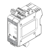
APP 412 is a controller for Flygt adaptive mixers or adaptive ultra low head pumps.

3.2 Approvals

Lists the certifications and approvals for the product, including CE, UL, CSA, and RCM.

3.3 Parts

Identifies and labels the physical components of the APP 412 controller, such as front connections and backplane connector.

3.4 The data plate

Details the information found on the product's data plate, including brand, MAC address, serial number, and part number.

Mechanical Installation

4.1 Do not install in an explosive zone

Notice warning against using the unit in environments with flammable, explosive, or chemically aggressive gases or powders.

4.2 Install the controller

Instructions for installing the APP 412 controller unit, including snapping it onto a DIN rail.

4.3 Install the controller and the gateways

Guidance on installing the controller along with FPG 415 gateways, referencing System Description for more details.

Electrical Installation

5.1 Precautions

Details critical safety precautions for electrical installation, including power isolation, grounding, and qualified personnel.

5.2 Connect the controller

Instructions for connecting the APP 412 controller, noting configurable terminals and referencing system documentation.

5.2.1 Connect a single unit

Step-by-step guide for connecting the controller to mixers/pumps, Ethernet, FOP 315 HMI, Modbus RTU, analog inputs, and digital inputs/outputs.

5.2.2 Set the switches

Details the correct settings for the NODE ADDRESS, MASTER/SLAVE, and TERM ON/OFF switches on the controller.

5.3 Connect the controller and the gateways

Instructions for connecting multiple units (gateways and controllers) in parallel or separately, including backplanes and power cables.

5.3.1 Connect the units

Details connecting multiple units, ensuring backplanes are connected, and connecting power cables to each unit.

5.3.2 Set the switches

Explains the correct switch settings for NODE ADDRESS, MASTER/SLAVE, and TERM ON/OFF for multiple units in a chain.

Operation

6.1 Startup and operation

Provides information on system operation, referring to the System Installation and Operation manual for detailed instructions.

6.2 LED indicators

Describes the meaning of various LEDs on the controller, including PWR, ALARM, RUN, COMMS, and RS-485, for normal operation.

Maintenance

7.1 Preventive maintenance

Covers preventive maintenance, including a DANGER warning for crush hazard and cleaning instructions.

7.2 Change the battery

Step-by-step instructions for changing the internal battery of the controller, including power off and lid removal.

Troubleshooting

8.1 The unit does not work

Provides a troubleshooting guide for common issues like the PWR LED not being lit or communication failures, with suggested remedies.

Technical Reference

9.1 Dimensions

Provides the physical dimensions of the APP 412 controller with graphical representation.

9.2 Environmental requirements

Details operating and storage temperatures, humidity, sunlight exposure, altitude, pollution degree, and installation location requirements.

9.3 IP rating

Explains the IP rating (IPXY) and its meaning regarding protection against foreign objects and water.

9.4 Electrical data

Presents key electrical specifications including supply voltage, tolerance, and current consumption.

9.5 RTC battery

Information about the internal battery for the real-time clock (RTC), including type, voltage, and capacity.

9.6 Terminals

Lists and describes the various terminals on the controller, their section, and function, including NODE ADDRESS and TERM.

Related product manuals