Do you have a question about the Xylem LOWARA and is the answer not in the manual?
Provides an overview, safety warnings, and usage instructions for the product.
Specifies the noise level of the equipment and its protection degree.
Details input supply, wiring, and earthing requirements for electrical connections.
Explains how to connect the unit to the water supply and system.
Details the adjustment of the flow regulating valve for optimal performance.
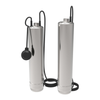
Explains the function of the low level float switch in preventing dry running.
Outlines checks for pump seal, seizing, noise, vibration, and motor overheating.
Covers checks for break tank cleanliness, water level, screws, and earth connections.
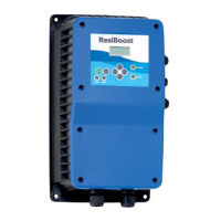
The Presfix Fill Set is a pressurisation unit designed for sealed heating, chilled water, and closed-condenser water systems. It ensures the proper pressurisation of these systems by automatically topping up water when needed. The unit is manufactured by Xylem Water Solutions UK Limited under the Lowara brand and complies with the Machinery Safety Directive (2006/42/EC), UK Health & Safety Regulations (2008 No.1597), Water Supply (Water Fittings) Regulations (1999), and BS7074 (parts 1, 2 & 3) Code of practice for heating and chilled water systems.
The primary function of the Presfix Fill Set is to maintain the correct water content and pressure within sealed heating, chilled water, and closed-condenser water systems. It operates in conjunction with a main pressurisation unit. When the main pressurisation unit detects that the system's water level is low, it sends a 230V supply to the Fill set, activating its pump. The Fill set then pumps water into the pressurisation set vessel, which is initially at atmospheric pressure. Once the main vessel reaches the correct water content, it signals the Fill set pump to switch off. The Fill set remains inactive until another signal from the main pressure set calls for more water.
The unit incorporates a break tank, which is supplied with water via a 1½" BSP ball valve. A flow regulating valve, typically set to approximately 5 l/m, controls the water flow into the break tank, ensuring that the incoming water supply can keep up with demand. This setting can be adjusted if the main water supply can provide a larger volume. A low-level float switch within the Fill unit monitors the break tank water level. If the water level drops too low, this switch signals the main pressurisation unit to cut power to the Fill unit, preventing the pump from running dry and sustaining damage.
The Presfix Fill Set is designed with a type AB air gap and a weir in the break tank. This design is a safety feature intended to spill water if a catastrophic failure occurs, preventing backflow into the main water supply. If direct spillage to the floor is not acceptable, the unit should be mounted on a tray with a discharge connection to a drain.
The Presfix Fill Set is dispatched mounted on a wooden pallet and covered in a protective film. It is recommended to keep the unit in its protective packaging until installation. The unit arrives pre-packaged and wired, ready for installation, having been fully run-tested at the factory under simulated site conditions. It should be sited in a dry, clean, well-ventilated area with good all-round access.
For electrical connections, the input supply to the switched spur is fed from the main pressurisation unit's output terminals 1, 2, and 3. This output is only active when the main pressurisation unit calls for water top-up. The low water cut-out float switch is wired back to the main pressurisation unit terminals 43 and 45. All connections must be made according to the provided wiring drawings, paying close attention to supply voltages. The cable size for the motor's full load current is specified on the duty plate, and non-power cabling should be limited to 2.5mm². It is crucial that the equipment is earthed to the building earth system, and the base frame must be earth-bonded directly. All wiring should enter the control boxes through appropriate cable glands. The product must never be operated with the control panel or switched spur lid removed.
For water supply and system connection, the 1½" BSP ball valve on the left side of the break tank should be connected to a suitable water supply with an approved stopcock. If the pressure at the ball valve is below 0.3 bar, a low-pressure orifice must be fitted. The 3½" plastic overflow pipe from the break tank must be extended to a position where an overflow will be noticed and rectified. The warning pipe must be capable of handling the incoming water volume; if not, a reducing valve should be fitted to the incoming water supply. The pressurisation port (½" BSP, right-hand side of the unit) connects to the main system expansion vessel fill point, with connection details found in the main pressurisation unit's Operation and Maintenance manual.
Commissioning involves several steps. It should be carried out in conjunction with the main pressurisation set commissioning details. The main system should be filled with water via a quick-fill loop to the system fill pressure. This filling loop must comply with local water authority bylaws and contain double check valves, and it must be completely removed after the system is filled. The pressurisation unit/Fill set must never be used to fill the system. The maximum running time for pumps fitted to the Fill set must not exceed 4 hours in any 24-hour period. The water supply feeding the Fill set break tank must be turned on. Water treatment crystals or chemicals must never be introduced to the system via the break tank. Finally, the pump must be fully evacuated of all air by removing the bleed screw and allowing water to escape until no air is present, then replacing the bleed screw.
To operate the unit, switch the main power supply to the pressurisation system to the "on" position, then turn the switched spur at the front of the Fill unit to the "on" position.
Regular maintenance is essential to ensure the longevity and proper functioning of the Presfix Fill Set.
The equipment operates at a noise level lower than 70dBA and has a protection degree of IP2X. It is important to note that handling, transportation, and installation of this equipment should only take place with the proper use of lifting equipment. The product must be stored in a frost-free, dry environment.
| Model | LOWARA |
|---|---|
| Category | Water Pump |
| Type | Centrifugal Pump |
| Application | Domestic, Industrial, Agricultural |
| Materials | Stainless Steel, Cast Iron |
| Flow Rate | Varies by model |
| Head | Varies by model |
| Power | Varies by model |
| Voltage | Varies by model |
| Frequency | 50 Hz / 60 Hz |