REAR
PANEL
CONNECTIONS
•
•
•
0
IJI
U -
10
2 3 4 5 6 7
9
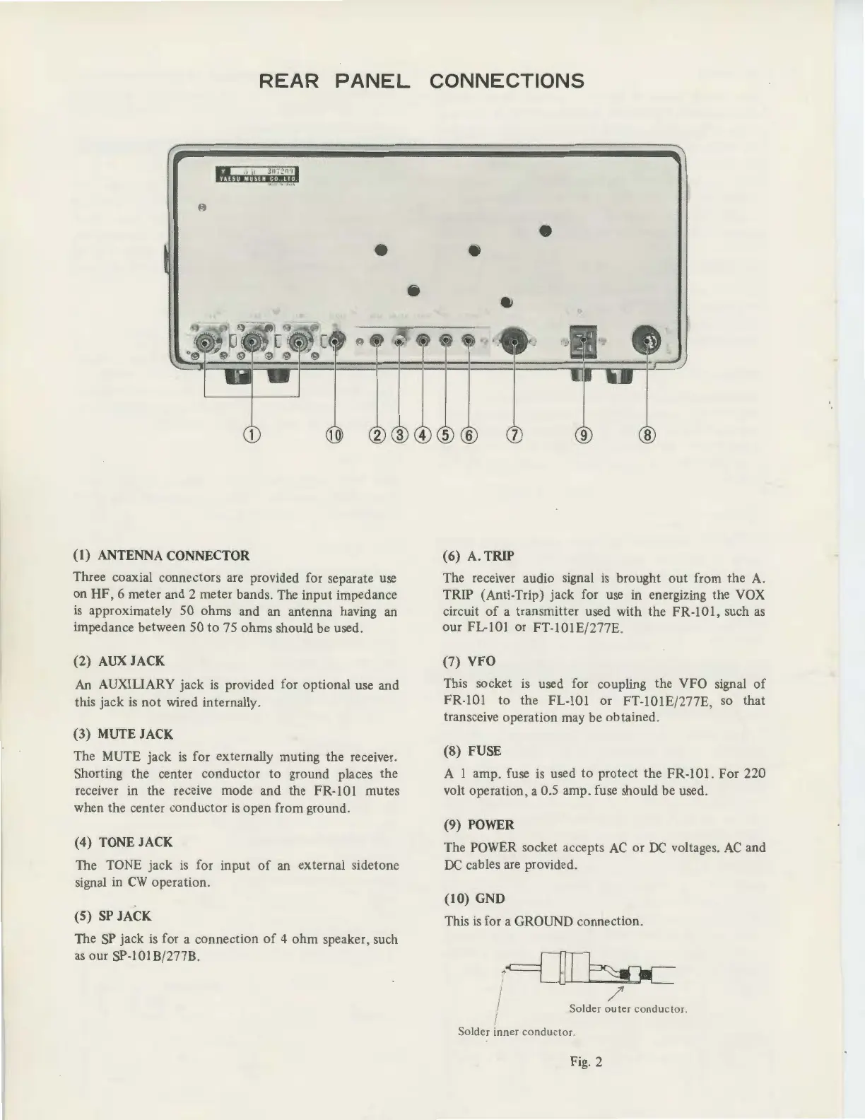
(1) ANTENNA CONNECTOR
Three coaxial connectors are provided for separate use
on HF,
6 meter and 2 meter bands. The input impedance
is
approximately
50
ohms and an antenna having
an
impedance between
50
to 75 ohms should be used.
(2) AUX JACK
An AUXILIARY jack
is
provided for optional use and
this jack
is
not
wired internally.
(3) MUTE JACK
The MUTE jack
is
for externally muting the receiver.
Shorting the center conductor to ground places the
receiver in the receive mode and the FR-101 mutes
when the center conductor
is
open from ground.
(4) TONE JACK
The TONE jack
is
for
input
of
an external sidetone
signal
in
CW
operation.
(5)
SP
JACK
The
SP
jack
is
for a connection
of
4 ohm speaker, such
as
our SP-101B/277B.
(6)
A.
TRIP
The receiver audio signal
is
brought
out
from the A.
TRIP (Anti-Trip) jack for
use
in energizing the VOX
circuit
of
a transmitter used with the FR-101, such
as
our FL-101 or FT-101E/277E.
(7) VFO
This socket
is
used for coupling the VFO signal
of
FR-101 to the FL-101 or FT-101E/277E,
so
that
transceive operation may be obtained.
(8) FUSE
A 1 amp. fuse
is
used to protect the FR-101.
For
220
volt operation, a 0.5 amp. fuse should be used.
(9) POWER
The POWER socket accepts
AC
or
DC
voltages.
AC
and
DC
cables are provided.
(10) GND
This
is
for a GROUND connection.
r
==[~
I Solder
~e
r
co
ndu
cto
r.
Solder inner condu
cto
r.
Fig. 2


 To Next Page