OPERATION
The receiving procedure
of
the FR-101
is
not
compli-
cated, however care should be exercised when tuning
to
insure
optimum
performance
of
the equipment. The
following paragraphs describe the procedures for the
operation
of
the receiver.
INITIAL CHECK
Before connecting the FR-101 .
to
a power source,
carefully examine for any visible damage. Check
that
all
modules and crystals are firmly in their sockets and
that
controls and switches are operating normally.
Be
sure
that
the voltage specification marked
on
the rear panel
matches the supply voltage.
FREQUENCY SELECTION
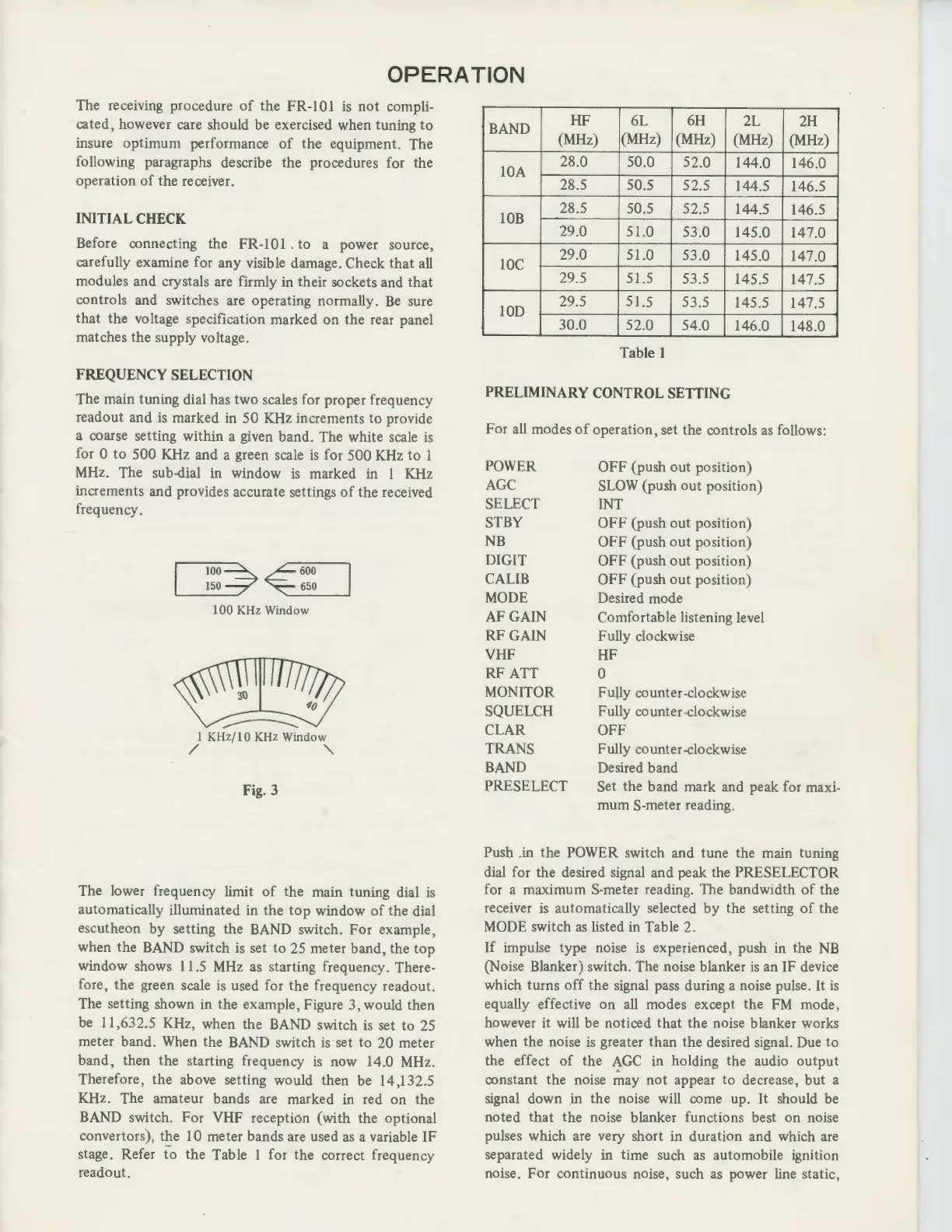
The main tuning dial has two scales for proper frequency
readout and
is
marked in
50
KHz increments
to
provide
a coarse setting within a given band. The white scale
is
for 0
to
500
KHz and a green scale
is
for
500
KHz
to
1
MHz. The sub-dial in window
is
marked
in
1 KHz
increments and provides accurate settings
of
the received
frequency.
100
~
,,,L
600
150-7
~
650
~--~
100
KHz Window
-------------
!
KHz
/
10
KHz
Window
/
"'
Fig. 3
The lower frequency limit
of
the main tuning dial
is
automatically illuminated in
the
top
window
of
the dial
escutheon by setting the BAND switch. For example,
when the BAND switch
is
set
to
25 meter band, the
top
window shows 11.5 MHz
as
starting frequency. There-
fore, the green scale
is
used for the frequency readout.
The setting shown in the example, Figure
3,
would then
be 11,632.5 KHz, when the BAND switch
is
set to 25
meter band. When the BAND switch
is
set
to
20
meter
band,
then the starting frequency
is
now 14.0 MHz.
Therefore,
the
above setting would then be 14 ,13 2
.5
KHz. The amateur bands are marked
in
red
on
the
BAND switch. For VHF reception (with the optional
converters), the 10 meter bands are used
as
a variable
IF
stage. Refer
to
the Table 1 for the correct frequency
readout.
HF
6L
6H
2L
2H
BAND
(MHz)
(MHz)
(MHz)
(MHz)
(MHz)
lOA
28.0
50.0
52.0
144.0
146.0
28.5 50.5
52.5
144.5 146.5
lOB
28.5
50.5
52.5
144.5
146.5
29.0
51.0
53.0
145.0
147.0
lOC
29.0
51.0
53.0
145.0
147.0
29.5
51.5
53.5
145.5
147.5
lOD
29.5 51.5
53.5
145.5
147.5
30.0
52.0 54.0
146.0
148.0
Table 1
PRELIMINARY CONTROL
SETIING
For all modes
of
operation, set the controls
as
follows:
POWER
AGC
SELECT
STBY
NB
DIGIT
CALIB
MODE
AF GAIN
RF GAIN
VHF
RF ATT
MONITOR
SQUELCH
CLAR
TRANS
BAND
PRESELECT
OFF (push out position)
SLOW
(push
out
position)
INT
OFF
(push
out
position)
OFF (push
out
position)
OFF
(push
out
position)
OFF
(push
out
position)
Desired mode
Comfortable listening level
Fully clockwise
HF
0
Fully counter-clockwise
Fully counter-clockwise
OFF
Fully counter-clockwise
Desired band
Set the band mark and peak for maxi-
mum S-meter reading.
Push .in the POWER switch and tune the main tuning
dial for the desired signal and peak the PRESELECTOR
for a maximum S-meter reading. The bandwidth
of
the
receiver
is
automatically selected
by
the setting
of
the
MODE switch
as
listed in Table 2.
If
impulse type noise
is
experienced, push
in
the
NB
(Noise Blanker) switch. The noise blanker
is
an IF device
which turns
off
the signal pass during a noise pulse.
It
is
equally effective
on
all modes except the
FM
mode,
however it will be noticed
that
the noise blanker works
when the noise
is
greater
than
the desired signal. Due
to
the effect
of
the
1-GC
in holding the audio
output
constant the noise may
not
appear
to
decrease,
but
a
signal down in the noise will come up.
It
should be
noted
that
the noise blanker functions best
on
noise
pulses which are very short in duration and which are
separated widely in time such
as
automobile ignition
noise. For continuous noise, such
as
power line static,


 To Next Page
 Loading...