the noise blanker will be
less
effective since the blanker
circuit has difficulty in distinguishing the noise from the
de
sired signal.
For VHF reception, set the VHF switch
to
the desired
band, either 6 or 2 meters. Set the
BAND
switch to the
10 meter band and peak the PRESELECTOR for maxi-
mum S-meter reading. The frequency .relation
is
listed in
Table
1.
When the (optional)
FM
unit
is
installed, advance
the SQUELCH control slowly until the back-ground
noise disappears with no signal input.
MODE
BANDWIDTH
CW-N
*
0.6 kHz/6
dB
1.5 kHz/ 60
dB
cw
RTTY**
LSB
2.4 kHz/6
dB
4.0 kHz/60
dB
USB
AM
·N
AMW*
6 kHz/6
dB
12
kHz/50
dB
FM
*
20 kHz/6
dB
45 kHz/50
dB
*
Wi
th o
pti
onal filter fo r FR-101 Sta
nd
ard type rece
iv
er
**With
option
al filter for FR-101 Sta
ndard
and
Delu
xe
type rec
eiv
ers.
Table 2
DIAL CALIBRATION
The calibration
of
the main tuning dial may vary slightly
from band
to
band due
to
the tolerance limits
of
the
heterodyne crystals. Therefore, a dial calibration knob
is
provided on the front panel. To set the calibration on a
given band and desired mode, proceed
as
follows:
1.
Set the
BAND
switch and the PRESELECTOR to the
desired band.
2. Set the CLAR switch
to
OFF position.
3. Push the CALIB switch in. A switch
is
located on the
top
of
AF unit inside the cabinet that selects either
the 25 KHz or 100 KHz calibrate signals. When the
switch
is
set
in
the direction
of
front panel, a
calibrate signal may be heard at
25
KHz intervals.
4. Set the 100 KHz dial in the window to the nearest
100 KHz or 25 KHz reading, then zero beat the main
tuning dial against marker signal while pressing the
DIAL LOCK. For
AM
or
FM
, the beat tone can
not
be heard. Therefore, the calibration should be made
for maximum S-meter reading. Since the
AM
and
FM
filters have a wide bandwidth, the calibration should
be made at the center
of
the passband
as
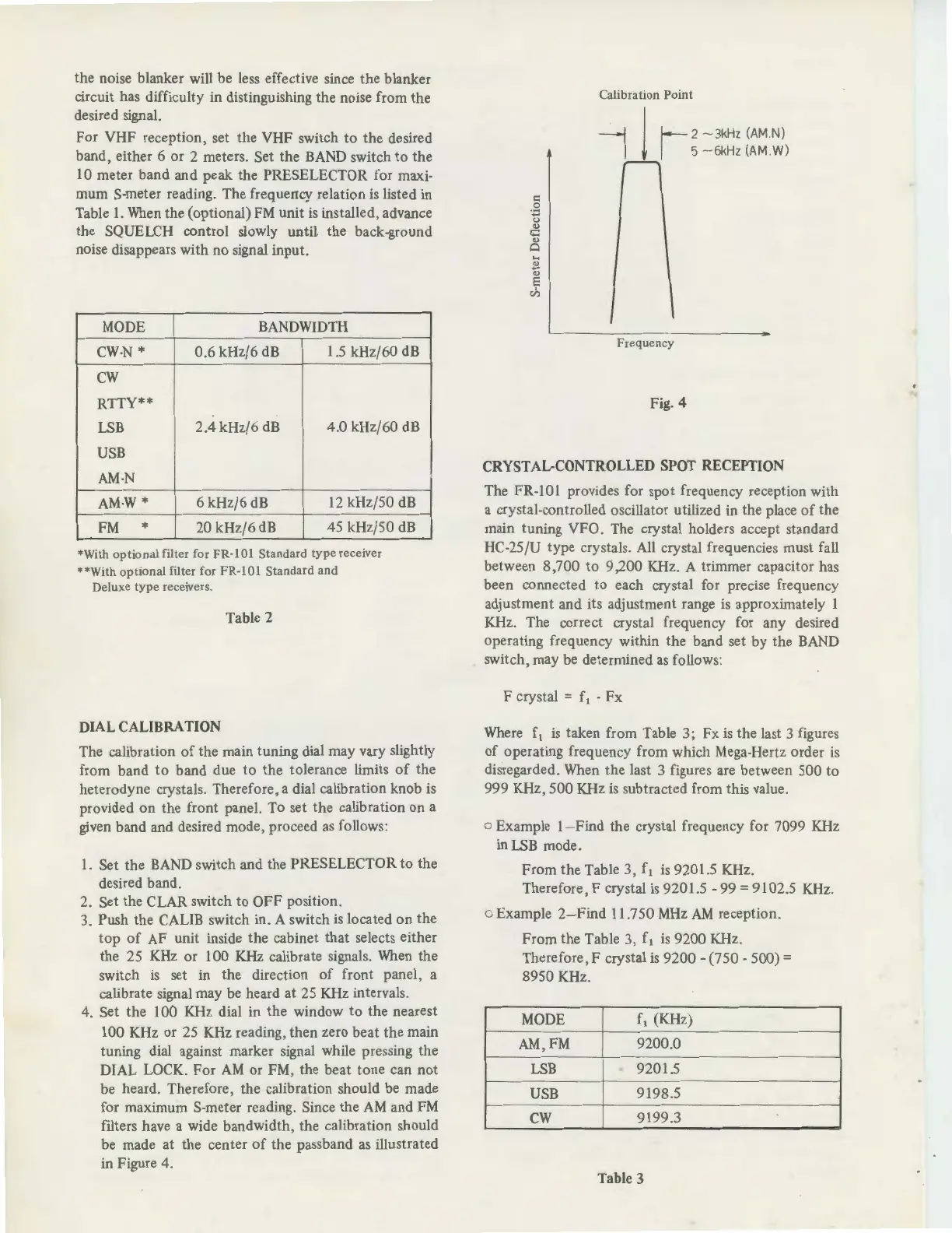
illustrated
in Figure 4.
=
.g
u
"'
..::
"'
Cl
Calibration Point
--j
j
f--
2
-3
kH
z (
AM
N)
I I 5 -
6kH
z (
AM
W)
Frequency
Fig. 4
CRYSTAL-CONTROLLED SPOT RECEPTION
The FR-101 provides for spot frequency reception with
a crystal-controlled oscillator utilized in the place
of
the
main tuning VFO. The crystal holders accept standard
HC-25/U type crystals.
All
crystal frequencies must fall
between 8 ,700
to
9 ,200 KHz. A trimmer capacitor has
been connected to each crystal for precise frequency
adjustment and its adjustment range
is
approximately 1
KHz. The correct crystal frequency for any desired
operating frequency within the band set by the
BAND
switch, may be determined
as
follows:
F crystal
= f
1
-
Fx
Where
f
1
is
taken from Table 3; Fx
is
the
la
st 3 figures
of
operating frequency from which Mega-Hertz order
is
disregarded. When the last 3 figures are between 500 to
999 KHz, 500 KHz
is
subtracted from this value.
o Example 1- Find the crystal frequency for 7099
KHz
inLSB mode.
From the Table 3,
f1
is
9201.5 KHz.
Therefore, F crystal
is
9201.5 - 99 = 9102.5
KHz.
o Example 2- Find
11
.750
MHz
AM
reception.
From the Table 3, f
1
is
9200 KHz.
Therefore, F crystal
is
9200 - (750 - 500) =
8950 KHz.
MODE
f
1
(KHz)
AM,FM 9200.0
LSB
.
9201.5
USB
9198.5
cw
9199.3
Table 3
·-


 To Next Page
 Loading...