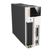
MS-LxP Series Hybrid Servo DriverVersion2.0 MS-LxP Series Hybrid Servo DriverVersion2.0
4
2. Terminal definition
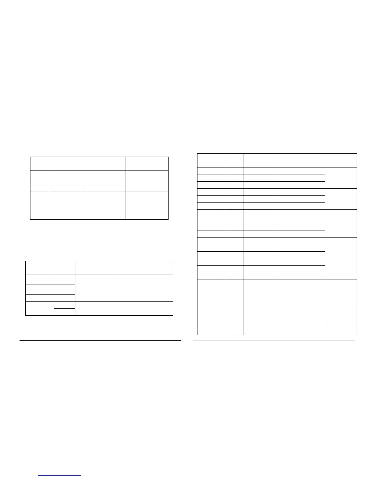
1).Power input terminal
No
Name Instruction Instruction
1 AC
Power input terminal
AC
2 AC
3 NC NC Don’t connect
4 BRK-
Externally connect
with brake resistor or
don’t connect
5 BRK+
2)Motor output terminals
The driver outputs power to motor through U, V, and W terminals. The
driver’s U,V and W can only connect with motor’s U,V,W resistance, cannot
connect with AC. And the motor’s U,V,W must connect with driver’s U,V,W
one by one, or the motor can’t work normally.
Cable color Terminal
name
Instruction Instruction
Brown U
Driver output
Connect with motor’
W.
Blue V
Black W
NO PE
GND terminal
Don’t connect
PE
3)Encoder feedback terminal
Connect motor’s encoder with driver through encoder cable
4) Definition of control signal terminal
Connection of cables and signals as below:
Cable color
Terminal instruction Instruction
Orange 1
5DR+
Direction input 5+
5
DR-
Negative direction input
Deep yellow 17
24DR+
Direction input 24V+
Purple 3 5PU+ Pulse input 5V+
signal
Purple-white 2 PU- Negative pulse input
Light purple 19 24PU+ Pulse input 24+
Deep brown 12 5MF+ Motor free 5V+
input signal
Deep
brown-white
11 MF-
input,
Deep blue 13 24MF+ Motor free 24V+
Black 10 5CLR_A+ over-
signal
Black-white 27 CLR_A- Negative over-
alarm clear input
Deep-green 29 24CLR_A+ Over-
input 24V+
Deep grey 7 PEND+
signal
Deep
grey-white
6 PEND-


 To Next Page
 Loading...