Copyright ©2018, 2020, 2021, ASSA ABLOY Access and Egress Hardware Group, Inc. All rights reserved. Reproduction in
whole or in part without the express written permission of ASSA ABLOY Access and Egress Hardware Group, Inc. is prohibited
For technical support contact Yale
®
at 800.438.1951 x5033 or support@yalelocks.com
5
Delayed Egress
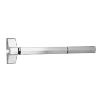
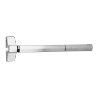
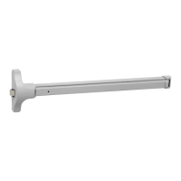
7100, 7200 Series Exit Device
Installation Instructions
8094700162000 04/21
2 End Cover and PC Board Assembly
1. Trim device to proper length as required.
36" Exit Device - 1" maximum can be trimmed
48" Exit Device - 6" maximum can be trimmed
2. Carefully slide circuit board assembly into end Cover to ensure indicator light (LED) is not bent.
3. Insert mortise cylinder into end cover with keyway horizontal, as shown.
4. Slide arming switch activator over mortise cylinder so activator legs are on each side of switch.
5. Insert flange of cylinder nut into arming switch activator to allow rotation of activator.
6. Tighten cylinder nut on mortise cylinder and to secure circuit board assembly.
7. Verify assembly by rotating key counter clockwise and clockwise. Key should move freely and
arming switch should trip for both rotation directions. If key does not rotate freely, verify cylinder
nut was placed in correct orientation. If arming switch does not trip, activator legs on arming
switch activator can be bent to reduce or increase rotational travel.
Figure 2
Cylinder Nut
Activator Legs
Tabs
Indicator Light
(LED)
Arming Switch Activator
Lens Cover
Cylinder Collar
(Order separately
when required)
1-1/8” (29mm)
Mortise Cylinder
1000-118-A02
(Order seperately)
Rear Cover
End Cap
Order Separately
1-1/8”
29mm
Typical Mortise
Cylinder
1000-118-A02
A02 Cam
1-1/2”
38mm
Collar
Cylinder and Collars
• Use standard 1-1/8” mortise
cylinder with A02 cam. Corbin
Russwin #1000-118-A02 collar
is not required.
• Use Corbin Russwin collar
270F15 for optional 1-1/4” long
cylinder.
• Use Corbin Russwin collar
654F07 for optional 1-1/2” long
cylinder.
To Power
Transfer
To Device Connection
Activator Legs
Arming Switch Activator
Circuit Board
Label
Circuit Board Assembly
 Loading...