EasyManua.ls Logo

Yale Delayed Egress 7100 Series

Yale Delayed Egress 7100 Series
28 pages
To Next Page IconTo Next Page
Loading...
7100, 7200 Series Exit Device
Delayed Egress
Installation Instructions
Copyright ©2018, 2020 ASSA ABLOY Access and Egress Hardware Group, Inc. All rights reserved. Reproduction in whole or
in part without the express written permission of ASSA ABLOY Access and Egress Hardware Group, Inc. is prohibited.
For technical support contact Yale
®
at 800.438.1951 x5033 or support@yalelocks.com
8094700162000 10/20
This product can expose you to
lead which is known to the state
of California to cause cancer and
birth defects or other reproductive
harm. For more information go to
www.P65warnings.ca.gov.
Attention Installer
Any retrofit or other field modification to a fire rated opening
can potentially impact the fire rating of the opening, and
Yale Locks & Hardware makes no representations or
warranties concerning what such impact may be in any
specific situation. When retrofitting any portion of an
existing fire rated opening, or specifying and installing a new
fire-rated opening, please consult with a code specialist or
local code official (Authority Having Jurisdiction) to ensure
compliance with all applicable codes and ratings.
WARNING
Available on the following devices:
Rim
Mortise
SquareBolt®
Concealed Vertical Rod
*Surface Vertical Rod
*Rod Guards Required (made by other manufacturers)
Question and Answer IconNeed help?

Do you have a question about the Yale Delayed Egress 7100 Series and is the answer not in the manual?

Yale Delayed Egress 7100 Series Specifications

General IconGeneral
BrandYale
ModelDelayed Egress 7100 Series
CategoryDoor Opening System
LanguageEnglish

Summary

Panic and Fire Rated Devices

Checklist

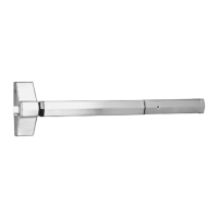
Initial checks and verification of device components before installation.

Required Components

List of essential components needed for the delayed egress system installation.

Optional Components

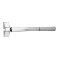
List of available optional components for enhanced functionality.

Electrical Specifications

Details on voltage, wire size, and power consumption for the device.

End Cover and PC Board Assembly

DIP Switch Settings

Installation of End Cover Assembly to Device

Device Mounting

Wiring Layout: InputOutput Wiring Descriptions

ElectroLynx Connector System for All Electrical Installation

Installing Delayed Egress Exit Device

ElectroLynx Wiring Options Overview with QC12 Hinge

ElectroLynx Wiring Deed with O Trim Monitor Option and QC12 Hinge

ElectroLynx Wiring Deed with Electrified Trim (ET) Option and QC12 Hinge

ElectroLynx Wiring Deed with S Latchbolt Monitor Option and QC12 Hinge

Non-ElectroLynx Door Prep

Wiring Diagram - Single Door Exit Only

Wiring Diagram - Single Door With Remote Inputs & Monitoring Outputs

Wiring Diagram - O Trim Monitor Entry with External Door Position Switch

Wiring Diagram - 690 F Electric Trim Control

Wiring Diagram - 691 F Electric Trim Control

Operating Instructions

Delayed Egress Mode

Describes the device's armed state and initial operation sequence.

Momentary Egress Mode

Details how to activate and use the momentary egress function.

Additional Options Non ElectroLynx Wiring

O Suffix

Explains the Outside Trim Monitor Switch functionality.

Latchbolt Monitor Switch

Describes the function of the Latchbolt Monitor Switch.

BOCA 15 Second Delay and BOCA 30 Second Delay

NFPA 101 Requirements: 30 Second Delay

Troubleshooting

Diagnostic LEDs

Explanation of the function of various diagnostic LEDs on the device.

Appendix: Legacy Boards

Related product manuals