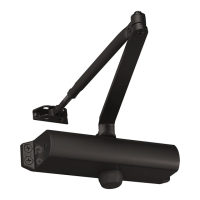
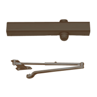
Option A – Regular Arm Installation
INSTALLATION
INSTRUCTIONS
Option A instructions: 1. Using the measurements from diagram A, mark
screw hole center locations. Mark four (4) hole locations on door for door closer
and two (2) hole locations on frame for arm shoe. 2. Drill pilot holes in door
and frame, drill 7/32″(5.5mm) diameter holes for wood screws or drill and tap
#7(.201″ diameter) for 1/4-20 machine screws. 3. Install adjustable forearm/arm
shoe to frame using screws (a) or (b). 4. Mount closer on door using screws
(c) or (d). SPEED ADJUSTING VALVES MUST BE POSITIONED TOWARD
HINGE SIDE. 5. Install main arm to top pinion shaft, perpendicular to door,
Secure tightly with arm screw/washer (e). 6. Adjust length of forearm so it is
perpendicular to frame when assembled to preloaded main arm. Secure forearm
to main arm with screw/washer (f). 7. Adjust closing speed, see page2 for
reference. 8. Snap pinion cap over shaft at bottom of closer or install (optional)
cover with small screw (j).
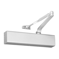
Option B – Top Jamb Installation
Option B instructions: 1. Using the measurements from diagram B, mark
screw hole center locations. Mark four (4) hole locations on door for door closer
and two (2) hole locations on frame for arm shoe. 2. Drill pilot holes in door
and frame, drill 7/32″(5.5mm) diameter holes for wood screws or drill and tap
#7(.201″ diameter) for 1/4-20 machine screws. 3. Install adjustable forearm/arm
shoe to door using screws (a) or (b). 4. Mount closer on frame using screws
(c) or (d). SPEED ADJUSTING VALVES MUST BE POSITIONED TOWARD
HINGE SIDE. 5. Install main arm to bottom pinion shaft, perpendicular to door,
Secure tightly with arm screw/washer (e). 6. Adjust length of forearm so it is
perpendicular to door when assembled to preloaded main arm. Secure forearm
to main arm with screw/washer (f). 7. Adjust closing speed, see page2 for
reference. 8. Snap pinion cap over shaft at bottom of closer or install (optional)
cover with small screw (j).
80-9316-8007-000 REV-1(3/17)