Do you have a question about the Yale 8800 Series and is the answer not in the manual?
Verify door hand and bevel for correct indicator installation.
Spindle cam positions for locks with deadbolts (8864 function).
Spindle cam positions for locks without deadbolts.
Adjust spindle cam orientation based on door hand.
Ensure thumbturn is correctly oriented for indicators.
Prepare door for function holes, size, and location.
Verify strike location, clean door pocket, slide lock into door.
Use template to mark indicator holes and drill.
Insert and fasten mounting plates, install roses and levers.
Screw indicator mounting plate to door with sheet metal screws.
Assemble and secure indicator assembly to mounting plate.
Thread cylinder into lock body and tighten clamp screw.
Tighten lock screws and attach outside front.
Test lock operation, latch, deadbolt, levers, and indicators.
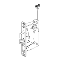
The Yale 8800 Series Mortise Lock is a robust and versatile locking solution designed for a variety of door applications. This installation manual details the process of integrating the mortise lock with sectional trim and V Series indicators, ensuring secure and reliable operation. The lock is engineered to provide enhanced security and control over access, making it suitable for commercial and institutional environments.
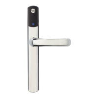
The 8800 Series Mortise Lock is a high-security mechanical lock that fits into a mortise pocket cut into the edge of a door. Its primary function is to secure a door by engaging a deadbolt and/or latch into a strike plate on the door frame. The lock mechanism is operated by various input methods, including cylinders, thumbturns, and coin turns, depending on the specific configuration and function ordered.
The lock body houses the internal components that control the latchbolt and deadbolt. When a key is turned in the cylinder or a thumbturn is operated, the internal mechanism retracts or extends the bolts, allowing the door to be opened or secured. The mortise design provides a higher level of security compared to standard cylindrical locks, as the lock body is fully enclosed within the door, making it more resistant to forced entry.
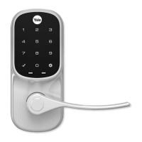
A key feature of the 8800 Series is its compatibility with V Series indicators. These indicators provide visual feedback on the lock's status (e.g., "Unlocked," "Locked," "Vacant," "Occupied," "Ouvert," "Fermé," "Libre"). This visual cue is crucial in environments where quick and clear communication of room status is necessary, such as restrooms, conference rooms, or private offices. The indicators can be configured for either inside or outside door installation, and their handing (left-hand, right-hand, etc.) can be adjusted to match the door's orientation.
The lock also supports different input types for the indicators, including cylinder, thumbturn, coin turn, or a blank/no-input option. This flexibility allows for customization based on specific access control requirements and user preferences. For instance, a cylinder input might be used on the outside for key access, while a thumbturn is used on the inside for quick egress.
The 8800 Series Mortise Lock is designed for ease of use and adaptability. Its installation process, while detailed, is straightforward for trained personnel, ensuring proper functionality and security. The lock's rehanding capability is a significant usage feature, allowing the installer to adjust the lock's orientation to match the door's hand and bevel. This ensures that the latchbolt is correctly oriented for smooth operation and that the indicator spindle cam aligns properly with the door's handing (RH/RHRB or LH/LHRB).
The indicators themselves are a key usage feature, providing clear and immediate visual status. For thumbturn indicators, a specific 12 o'clock position is recommended for installation, ensuring consistent and intuitive operation. The display slide slot and spindle cam are integral to this visual feedback system, allowing the indicator to accurately reflect the lock's state.
Levers are installed on both the inside and outside of the door, providing ergonomic and convenient operation. The use of plastic bushings and rose adapters ensures smooth lever action and a clean aesthetic finish. The set screws for the levers secure them firmly to the spindle, preventing looseness over time.
The cylinder installation is critical for key-operated functions. The cylinder threads into the lock body until flush with the indicator escutcheon surface, and a cylinder clamp screw secures it. The Yale logo on the cylinder must be horizontal and on top, serving as a visual guide for correct orientation. For double cylinder functions, two cylinders are installed, one on each side of the door, providing key access from both directions.
The lock's design also accommodates interchangeable core cylinders, offering flexibility for rekeying without disassembling the entire lock. This is particularly useful in facilities that require frequent key changes or master keying systems.
A functional check is an essential step after installation to ensure all components operate correctly. This involves verifying key rotation, latch retraction, deadbolt throw, and lever operation. The indicator's status display is also checked to confirm it accurately reflects the locked and unlocked states. This systematic check guarantees that the lock performs as intended, providing reliable security and convenience for end-users.
The 8800 Series Mortise Lock is built for durability and long-term performance, with several design considerations that facilitate maintenance and longevity. The robust construction of the lock body and components minimizes wear and tear, reducing the need for frequent repairs.
During installation, the importance of cleaning out the door pocket and door edge of debris is highlighted. This preventative measure ensures that no foreign particles interfere with the lock's internal mechanisms, which can lead to premature wear or malfunction. Similarly, ensuring the door surface is free of chips and debris around the indicator holes helps the indicator sit flat against the door, preventing damage and ensuring smooth operation of the display slide.
The use of specific screw types, such as #8-32 x 1-1/4" screws for mounting plates and #6 x 3/8" sheet metal screws for the indicator mounting plate, ensures secure fastening and prevents loosening over time. Torx security screws are recommended for securing the indicator assembly, adding an extra layer of tamper resistance and ensuring the indicator remains firmly in place.
The rehanding process, while part of installation, also serves as a maintenance-friendly feature. If a door's handing changes or if the lock needs to be moved to a different door with a different handing, the lock can be reconfigured without requiring a new unit. This flexibility extends the lifespan of the lock and reduces replacement costs.
The ability to easily remove and re-seat the retaining pad and spindle cam during rehanding or adjustment simplifies internal access for minor repairs or adjustments. The clear instructions for positioning the spindle cam and sliding it into the display slide slot ensure that these internal components can be correctly reassembled.
Regular functional checks, as outlined in the manual, are a key maintenance practice. By periodically testing the key, latch, deadbolt, and levers, potential issues can be identified early and addressed before they escalate into major problems. The instruction to "DO NOT FORCE if resistance is encountered" is a critical maintenance guideline, preventing damage to the lock's internal mechanisms and guiding the user to troubleshoot the issue (e.g., recheck handing) rather than applying excessive force.
The provision of a detailed indicator part list, including various escutcheon types, indicator windows, display assemblies, and spindle cams, simplifies the process of ordering replacement parts. This ensures that individual components can be replaced if damaged or worn, rather than requiring the replacement of the entire lock assembly, contributing to cost-effective maintenance.
Overall, the Yale 8800 Series Mortise Lock is designed for reliable operation with features that support both initial setup and ongoing maintenance, ensuring a long and secure service life.
| Type | Mortise Lock |
|---|---|
| ANSI Grade | Grade 1 |
| Function | Entry, Classroom, Passage, Storeroom |
| Material | Steel |
| Backset | 2-3/4" |
| Door Thickness | 1-3/4" |
| Latchbolt | 1/2" Throw |
| Deadbolt | 1" Throw |
| Handing | Reversible |