Copyright ©2020 ASSA ABLOY Access and Egress Hardware Group, Inc. All rights reserved. Reproduction in whole or in part
without the express written permission of ASSA ABLOY Access and Egress Hardware Group, Inc. is prohibited
For technical support contact Yale
®
at 800.438.1951 x5033 or support@yalelocks.com
3
Installation Instructions
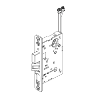
8800 Series
Mortise Lock
80-8800-0016-000 12/20
2 Indicator Variants
4 Rehanding Indicator (If required)
Depending on function and option ordered,
indicators are provided in the following
variations, these instructions detail how to install
with cylinder, however other variations follow
similar instructions. (Figure 1)
Contact factory for any questions.
Figure 1
Cylinder - For
installation
on inside or
outside of door.
Thumbturn -
For installation
on inside of
door.
Coin Turn - For
installation
on outside of
door.
No input / blank -
For installation on
inside or outside
of door.
3 Lock Set Configuration
To re-hand lock, see instructions on lock body.
LH
Left Hand
Hinges Left
Open Inward
RH
Right Hand
Hinges Right
Open Inward
LHRB
Left Hand
Reverse Bevel
Hinges Left
Open Outward
RHRB
Right Hand
Reverse Bevel
Hinges Right
Open Outward
Figure 2
Verify hand and bevel of door. (Figure 2)
Spindle Cam Position for Locks with Deadbolt
(*includes 8864 function)
Outside Indicator Inside Indicator
Door Hand LH/LHRB
Spindle Cam Position for Locks without Deadbolt
(*Does not include 8864 function)
Door Hand LH/LHRB
Figure 3
Note:
Stand on outside of locked door when determining door hand.
Next, verify inside and/or outside indicators are handed correctly,
using Spindle Cam Position chart. (Figure 3) If they are handed
correctly, skip to Step 5 “Prepare Door”.
If they are not handed correctly:
1. Remove retaining pad and spindle cam from assembly.
(Figure 4)
2. Position spindle cam in correct direction for door hand.
(Figure 3)
Important:
• For thumbturn indicators, make sure thumbturn is positioned
in the 12 o’clock direction as shown. (Figure 5)
3. Slide spindle cam post into correct slot of display slide.
(Figure 4)
4. Re-seat retaining pad into original position.
5. Return indicator to the vacant/unlocked position for
installation.
Thumbturn
Position
Figure 4
Figure 5
Retaining Pad
Spindle cam
Display
slide slot
Door Hand RH/RHRB
Inside Indicator Outside Indicator
Inside Indicator Outside Indicator
Door Hand RH/RHRB
Outside Indicator Inside Indicator
 Loading...