•
ERP22-35VL (ERP045-070VL) (A976)
•
ERP15-20VT (ERP030-040VT) (G807)
•
ERP16-20VF (ERP30-40VF) (A955)
•
ERP40-50VM, ERP50-55VM6 (ERP080-120VM, ERP100VML) (A985)
•
ERC40-55VH (ERC80-120VH) (A938)
See Main Control Valves 2000YRM1439, Calibration Menu for lift truck models
•
ERC16-20VA (ERC030-040VA) (A969)
See Main Control Valves 2000YRM1520, Calibration Menu for lift truck models
•
ERP13-15VC (ERP025-030VC) (B888)
See Diagnostic Troubleshooting Manual 9000YRM1377 for lift truck models
•
ERP80VN, ERP80VN9, ERP90VM (A410)
4
With no load on the forks, raise them, if they are not already raised.
5
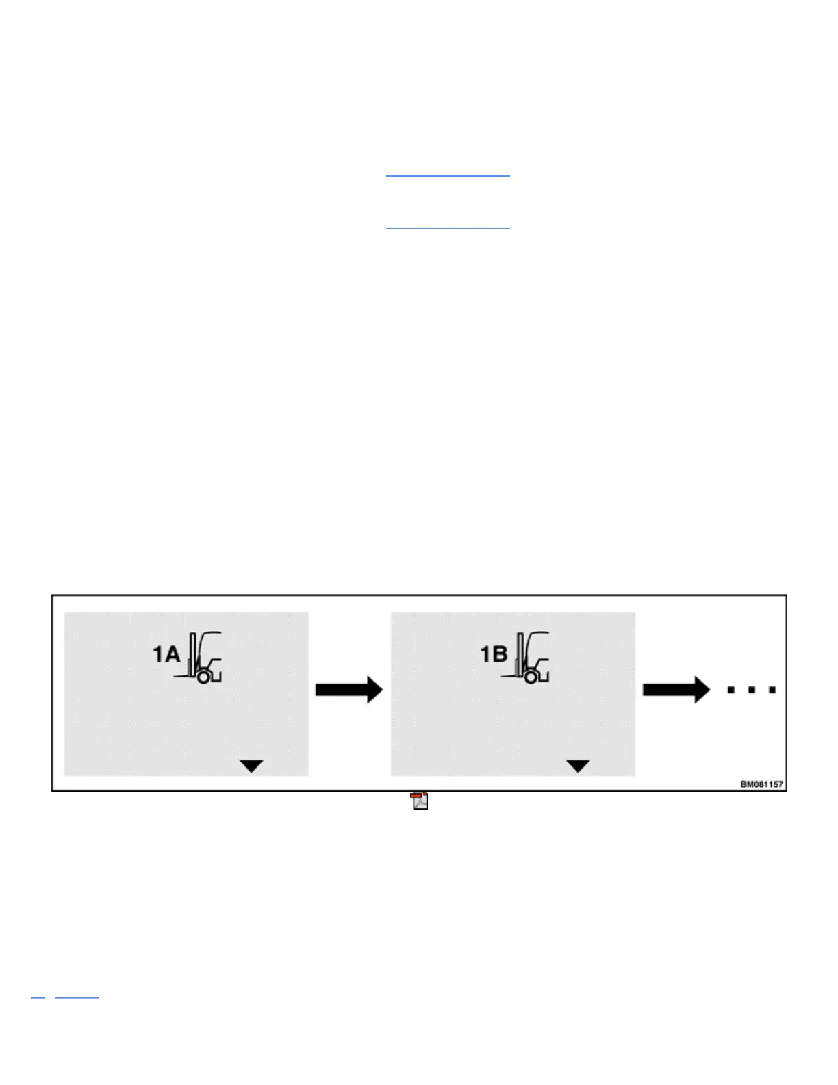
When prompted, move the lever toward the mast, the A direction, until the forks begin to creep. Creep
means moving the forks as slowly as possible. Press the Enter Key and the system records the valve
reading.
6
When prompted, move the lever toward the rear of the truck, the B direction, until the forks begin to
creep and press the Enter Key. The system records the valve reading. Steps 5 and 6 provide the
hydraulic input for function 1.
NOTE: If a valve reading is not within the acceptable range, an abort message appears. Press any
key to continue.
7
Continue the process for functions 2, 3, and 4 as prompted by the system. The system records the valve
readings for each function, and when this calibration process is completed, returns to the Calibration
Menu.
Figure 32. E-Hydraulic Valves
STEERING WHEEL CENTER POINT CALIBRATION
The steering wheel center point is the position to which the system adjusts the steering wheel while the lift
truck is being driven straight ahead.
NOTE: This calibration must be done by a supervisor or service technician and is only available on
trucks equipped with the Synchronized Steering function.
Figure 33 shows the screen display during a Steering Wheel Center Point calibration.