4
When prompted, use the numeric keys to enter the known load weight in lb or kg units, as indicated in
the load weight icon. Use a load weight that is between 1,000 lbs (450 kg) and 16,000 lbs (7,260 kg).
NOTE: Do not exceed the truck's rated capacity.
5
Press the Enter Key.
6
When prompted, position the load by adjusting the tilt and height of the mast and forks to the load
weight height.
7
Press the Enter Key. The system stores the new setting and returns to the Calibration Menu.
RETURN TO SET TILT STOP POINT CALIBRATION
NOTE: This calibration must be done by a supervisor or service technician and is only available on
trucks that have the Return to Set Tilt feature.
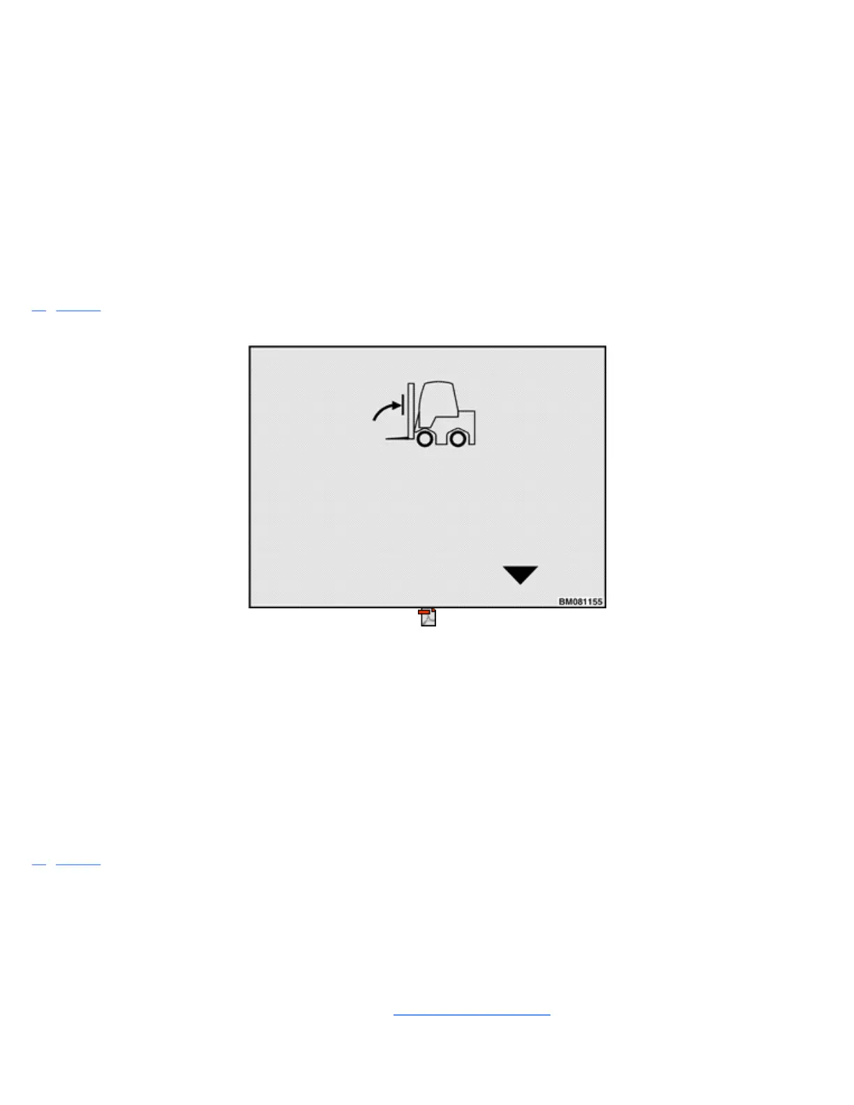
Figure 31 shows the screen display during a Return to Set Tilt Stop Point calibration. To calibrate Return to
Set Tilt Stop Point:
Figure 31. Return to Set Tilt Stop Point Sequence
1
Starting from the Calibration Menu, scroll to the Return to Set Tilt Stop Point screen and press the
Enter Key.
2
When prompted, position the mast at the desired tilt angle.
3
Press the Enter Key. The system records the new setting and returns to the Calibration Menu.
E-HYDRAULIC AND MANUAL VALVE THRESHOLD CALIBRATION
NOTE: This calibration must be done by a supervisor or service technician.
Figure 32 shows how the E-Hydraulic Valve calibration sequence starts with the 1A function, followed by the
1B function, and so on. The screen display changes from one function to the next as the user calibrates these
control valves. To calibrate the E-Hydraulic and manual valves:
1
Turn key or keyless switch to ON position.
2
Perform an air bleed operation by exercising all functions until they operate smoothly.
3
Starting from the Calibration Menu, scroll to the E-Hydraulic Valves screen and press the Enter Key.
See Main Control Valves 2000YRM1334, Calibration Procedure for lift truck models
•
ERC22-35VG (ERC045-070VG) (A968)