Maintenance and Repair 1300 YRM 1330
Figure 15.
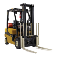
Removing the Cap
5. Usingagri
nd stone, slightly bevel the end of a 7/16
x2inchrol
l pin. Allow pin to cool.
6. Carefully
position roll pin to piston. Drive roll-pin
into cavit
yofpistonwithanylonfacedhammer.
NOTE: It ma
y be helpful to apply compressed air to the
service br
ake line port (as with removing the cap) AF-
TER the pi
ston has been pulled to the top end of the
brake cyl
inder.
NOTE: Mak
e note of the piston and seal orientation dur-
ing remov
al.
7. Pull roll
-pin (and piston) from cylinder using pliers.
NOTE: Mak
e note of the cylindrical pin orientation dur-
ing remov
al.
8. Remove cy
lindrical pin from beneath piston.
9. Inspect c
ylinder walls for pits, cracks, and other
damage.
NOTE: Ins
tall the cylindrical pin in the orientation noted
during r
emoval.
10. Lightly l
ubricate cylindrical pin with multipurpose
grease a
nd install into brake cylinder as noted dur-
ing remo
val.
NOTE: An
ew brake piston and new seal should be used
when rep
airing the brake cylinder assembly. Make sure
the new p
iston and new seal are oriented as noted when
remove
d.
11. Lightl
y lubricate new piston seal with multipurpose
grease
and install in new brake piston as noted dur-
ing rem
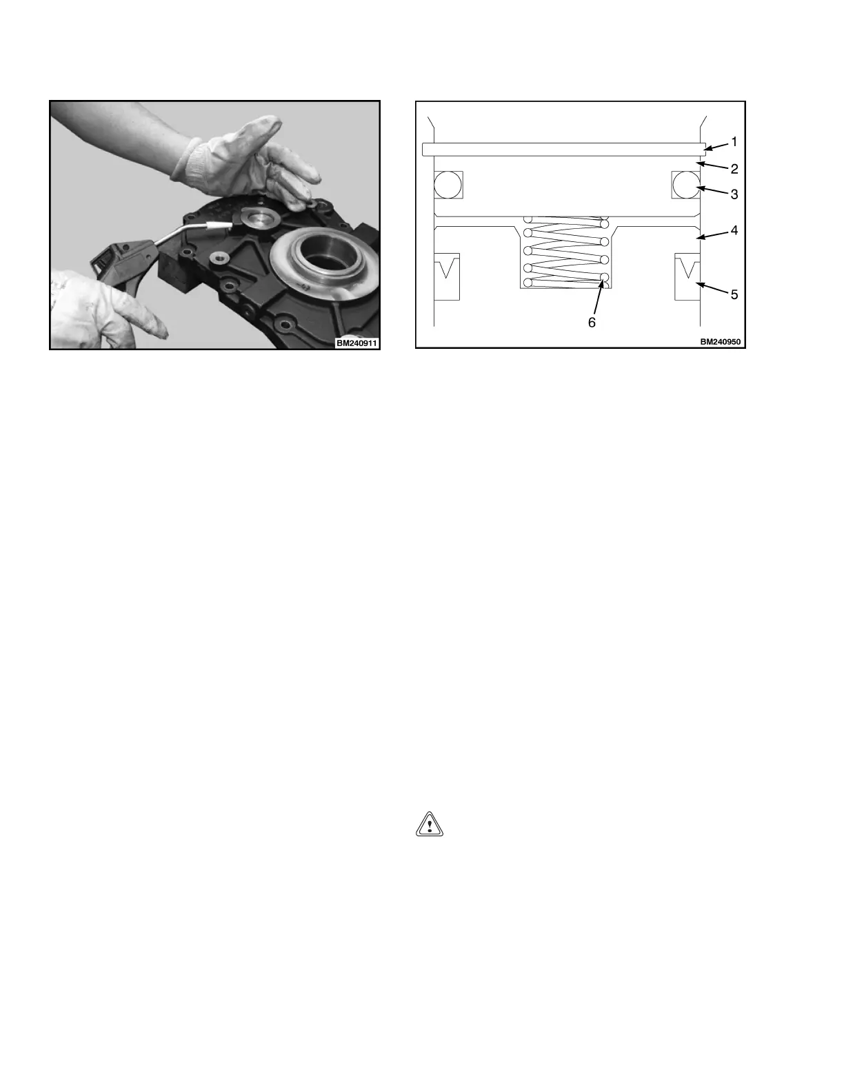
oval. See Figure 16.
1. SNAP RING
2. CAP
3. O-RING
4. PISTON
5. SEAL
6. SPRING
Figure 16. Piston Seal Orientation
12. Install new brake piston (and seal) into brake cylin-
der.
13. Place spring into cavity in piston by hand.
14. Lightly lubricate new O-ring with multipurpose
grease and install on cap as noted during removal.
NOTE: Make sure the cap is oriented as noted when
removed.
15. Install cap into brake cylinder.
16. Press cap into cylinder, to expose snap ring groove,
and install snap ring on brake piston.
NOTE: It is recommended to verify the torque on the
transaxle cover capscrews before reinstalling the trac-
tion motor. See section Cover to Housing Seal.
17. Install brake and traction motor on transaxle and
install transaxle on lift truck. See section Install
Transaxle to Frame.
CAUTION
Make sure the lift truck is blocked at the same
height as with the drive tire installed to ensure the
proper fluid level reading.
18. Check transaxle fluid level. See section Fluid Level
Check.
19. Install drive tire and tighten lugs to 170 N•m
(125 lbf ft). Test lift truck for proper operation.
12
 Loading...