Cylinder Head, Camshaft, and Valve Mechanism Repair 600 YRM 496
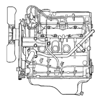
1. CYLINDER HEAD
2. RETAINING RING
3. VALVE GUIDE
Figure 13. Valve Guide Inspection
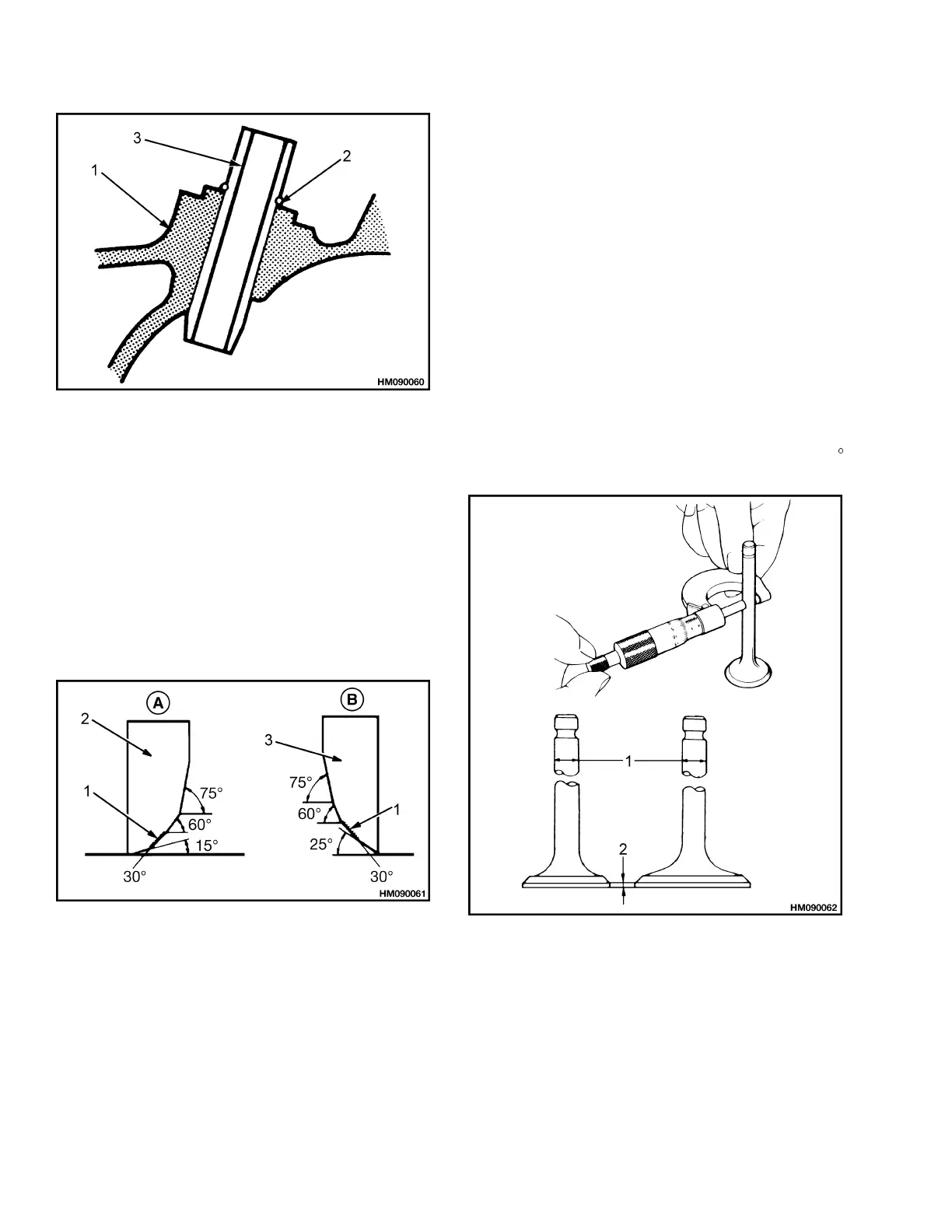
Valve Seats
1. Inspect condition of valve seats. If valve seats have
cracks, cylinder head must be replaced.
2. If valve seats are in good condition, check contact
pattern of valve and valve seat. Use valve seat
grinder to make sure valve seats are within spec-
ifications shown in Figure 14. Use valve compound
to make sure valves fit seats.
A. EXHAU
ST
B. INTAK
E
1. VALVE SEAT
WIDTH
2. EXHAU
ST VALVE
SEAT
3. INTAKE VALVE
SEAT
Figure 14. Valve Seat Specifications
Valves
1. Inspect stem of each valve for wear. Use microme-
ter to measure outside diameter of stem. See Fig-
ure 15.
Minimum dimension for intake valve is 7.980 mm
(0.3142 in.). Minimum dimension for exhaust valve
is 7.975 mm (0.3140 in.).
2. Inspect valves for cracks, burned faces, and distor-
tion. Inspect seat face of valves for wear and dam-
age.
3. Measure thickness of valve head. Minimum
thickness for intake valve is 0.5 mm (0.020 in.).
Minimum thickness for exhaust valve is 1.0 mm
(0.040 in.).
If valves need grinding, correct surface angle is 30
for both intake and exhaust valves.
1. DIAMETER 2. THICKNESS,
VALVE HEAD
Figure 15. Valve Inspection
6
 Loading...