engaged, the spacer and the brake shoes of the other
clutch are separated and are lubricated by cooling oil.
When inching pedal operates the inching valve, part of
or most of the oil flowing into clutch is drained to the oil
tank through inching valve, of the oil to torque
converter is the same as in neutral position.
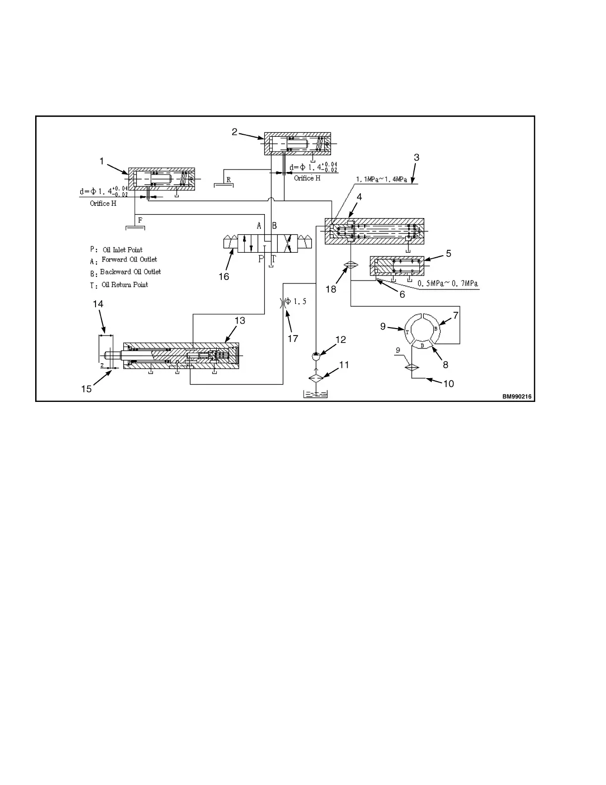
1. OVERFLOW PRESSURE BUFFER VALVE
2. BUFFER VALVE
3. MAJOR OIL PRESSURE
4. MAJOR PRESSURE ADJUSTING VALVE
5. OVERFLOW VALVE
6. OVERFLOW PRESSURE
7. IMPELLER
8. GUIDE WHEEL
9. TURBINE
10. TO LUBRICATING OIL CIRCUIT
11. ROUGH OIL FILTER
12. OIL PUMP
13. INCHING VALVE
14. CLUTCH PRESSURE REDUCTION FINISHES
15. CLUTCH PRESSURE REDUCTION STARTS
16. ELECTROMAGNETIC REVERSING VALVE
17. THROTTLE ORFICE
18. FINE OIL FILTER
Figure 13. Transmission Hydraulic Schematic
SPEED REDUCER AND SPEED
DIFFERENTIAL
Speed Reducer
The speed reducer is located on the front of the
transmission case (see Figure 14). This mechanism
reduces the rotating speed of output shaft and
increased the torque transmitted from the output shaft.
It sends this torque to the speed differential. The
speed reducer is composed of a small spiral bevel
gear on the output shaft, a large spiral bevel gear, and
a small gear shaft. The large spiral bevel gear is
mounted on the small gear shaft through spline while
the two ends of small gear shaft are both supported
with tapered roller bearing, and a gasket is used to
adjust the clearance.
Hydraulic Transmission Case and Torque Converter 8000 YRM 2199
16
 Loading...