When the lift is commanded, the high-pressure fluid
enters through the bottom part of lift cylinder, pushing
up the piston attached to the mast and raising the
inner mast along with the lift chain. When lower is
commanded, the fluid under the piston will flow out
under the weight of the forks and cargo, and the inner
mast will be lowered. The oil drained out from lift
cylinder is controlled by velocity fuse, and returns to
tank through multi-way valve.
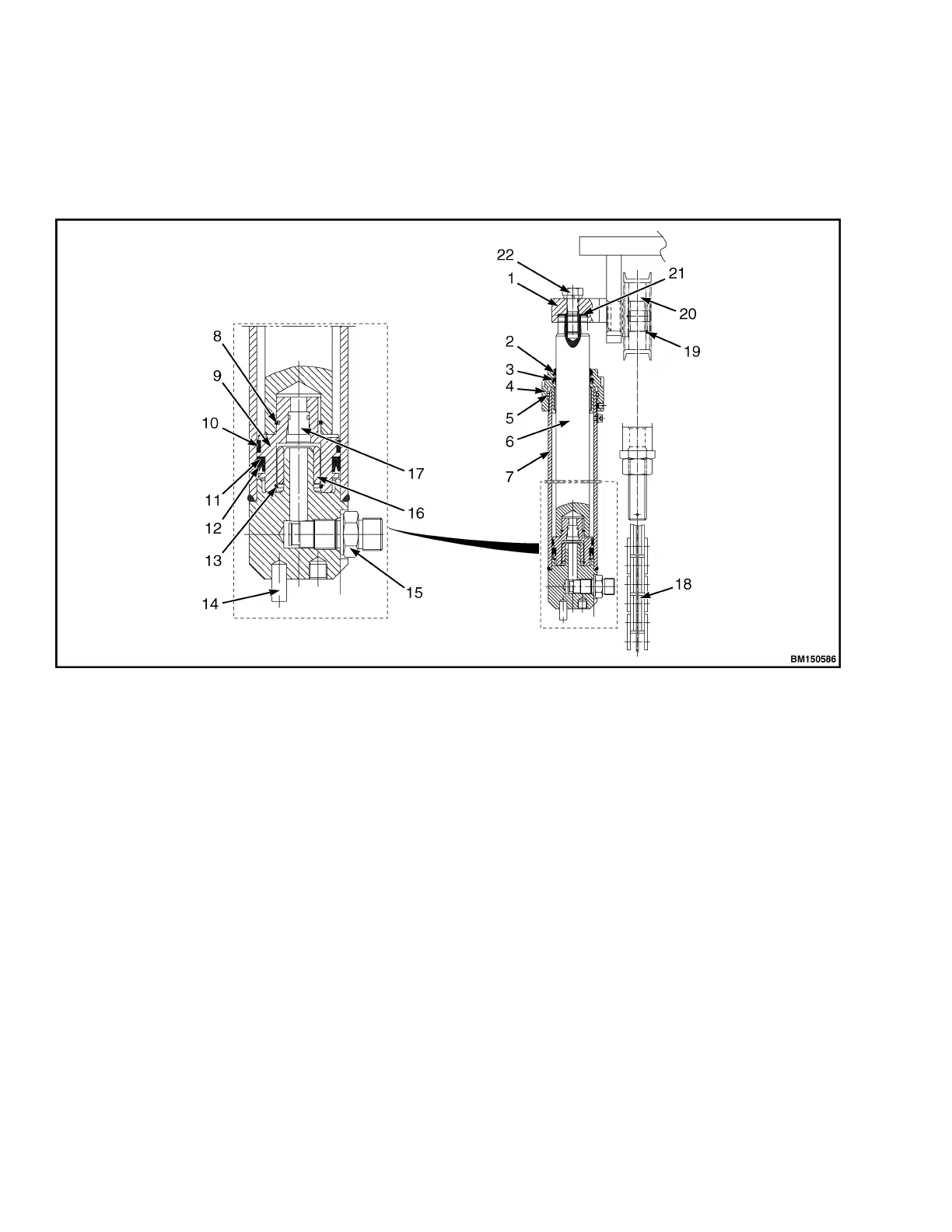
1. BEAM
2. WIPER
3. SHAFT SEAL
4. CYLINDER COVER
5. O-RING
6. CYLINDER ROD
7. CYLINDER BODY
8. O-RING
9. PISTON
10. SUPPORT RING
11. RETAINER RING
12. SEAL RING
13. RETAINER RING
14. LOCATER PIN
15. VELOCITY FUSE
16. VALVE SLEEVE
17. CHECK VALVE
18. HOIST CHAIN
19. RETAINER RING
20. ROLLER SPROCKET
21. SHIMS
22. BOLT
Figure 45. Lifting Cylinder
There is one velocity fuse on the bottom of the lift
cylinder (see Figure 46). It is designed to prevent load
from sudden drop, in the event that a hose carrying
hydraulic oil should suddenly fail. The fluid from lift
cylinder passes through the velocity fuse, and the oil
holes around the spool valve generates pressure
difference. When this pressure difference is smaller
than the spring force, the spool valve will not act. If the
high-pressure hose fails, a significant pressure
difference is formed collapsing the spring and blocks
off most oil flow back to tank , helping to prevent an
accident.
Hydraulic System 8000 YRM 2199
48
 Loading...