8
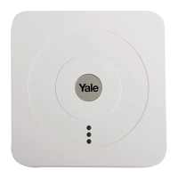
Mounting the Hub
The Hub can be free standing, either vertically or
horizontally on a at surface with access to mains socket
and broadband internet router.
It is also suitable for wall mounting. Using the two holes on
the mounting back plate, mark the position of the holes.
Drill two holes and x with the screws and plugs provided.
Hook the Hub onto the plate.
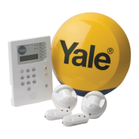
Check Accessories Range
Find a location where the device is to be mounted, see
section “Location Planning” for suggestions.
Before proceeding to mount the devices physically, check
that the Hub will receive the system radio transmissions by
doing a simple radio range test.
Go to the app menu, select Settings > Alarm Settings >
Test then select “Walk Test”.
Hold the accessories in the desired location and press the
Test/Learn button (see below) on the accessories.
• KEY PAD: Press button 8 + 9 together for 1 second.
• ALL OTHER accessories. Hold the accessories in the
desired location and press the test button for 1 second
If the sensor signal reached the Hub, it will show up on the
app screen.
When you are happy that all your accessories can
communicate with the Hub, please proceed to mounting
the accessories.
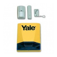
Note: Siren does not have a range test and will not appear
in the app device list. To test, arm/disarm the system. If the
siren beeps/ashes, a signal is being received successfully.
PIR Motion Detector
1. Open the PIR by loosening the bottom screw. Knock
out the relevant holes on the base where the plastic is
thinner. The center 2 knockout holes are for at wall
mounting while the 4 side holes are for corner mounting.
2. Drill holes into the wall using the knockout holes on the
base as a template.
3. Fit wall plugs and secure the PIR base with the screws
provided.
4. Fit the PIR back together and tighten bottom screw, the
PIR installation is complete.
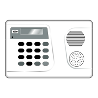
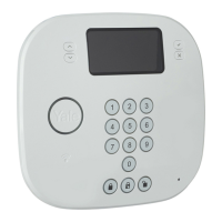
Mounting the Key Pad
1. Knock out the xing holes. Drill holes into the wall using
the xing holes as a template.
2. Fit wall plugs into the wall and x back cover with the
screws provided. Fix front of the Key Pad onto the
back plate.
Mounting Accessories
4
10
Mounting other devices
Find a location where the device is to be mounted,
see section “Location Planning” for suggestions.
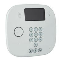
Mounting the Keypad:
Fixing Slots X 2
Keypad
Cradle Open
1 Drill holes into the wall using the fixing slots as a
template.
2 Fit wall plugs into the wall and fix cradle with the
screws provided.
3 Slide the keypad into the cradle
4 Close the cradle cover so the logo is facing you
Mounting the PIR
1 Open the PIR by loosening the bottom screw.
Knock out the relevant holes on the base where
the plastic is thinner. The center two knockout
holes are for flat wall mounting while the 4 side
holes are for corner mounting.
Corner fixing
knockouts X 4
Wall fixing
knockouts X 2
2 Drill holes into the wall using the knockout holes on
the base as a template.
3 Fit wall plugs and secure the PIR base with the
screws provided.
4 Fit the PIR back together and tighten bottom
screw, the PIR installation is complete.
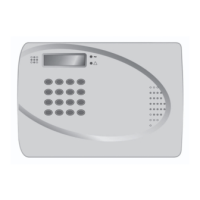
Before proceeding to mount the devices
physically, check that the control unit will
receive the system radio transmissions by
doing a simple radio range test.
• Put the control unit into walk test mode.
• KEYPAD: press the arm button.
• HELP BUTTON: press the button.
• ALL OTHER DEVICES: Hold the device
in the desired location and press the
learn/test button, the control unit should
respond with a chime.
• When you are satised that the devices
work in your chosen locations, proceed
with the installation as described.
• If the control unit does not respond,
the location may be out of range, try
alternative locations until reliable radio
contact is obtained.
i
The PIRs have a built-in sleep timer to save
battery power. If there is no movement in front
of the PIRs for 1 minute, the PIRs will become
‘ready to signal’ and movement will now be
reported. The PIRs will sleep for 1 minute after
reporting.
Any movement detected in sleep time will not be
reported and will extend the sleep period by a
further 1 minute.
i
Corner fixing
knockouts X 4
Wall fixing
knockouts X 2
 Loading...