Frame Repair 100 YRM 760
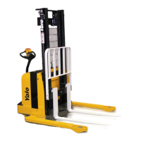
Legend for Figure 1
1. STUD
2. SPRING
3. CUPPED WASHER
4. RETAINER
5. NUT
6. COVER
7. HINGE PIN
8. RH DOOR
9. THUMB SCREW
10. LH DOOR
11. BATTERY ROLLER
12. B ATTERY PANEL
13. BASE ARM WELDMENT (OS030BE, OS030BF,
OS030EC, AND OS030EF SHOWN)
14. FRAME WELDMENT
Frame Repair
REMOVE AND DISASSEMBLE
WARNING
Forklift truc
k frames and components may have
polyurethane
paint. Welding, burning, or other heat
sufficient to
cause thermal decomposition of the
paint may rel
ease isocyanates. These chemicals
are allergic
sensitizers to the skin and respira-
tory tract; o
verexposure may occur without odor
warning. Sho
uld work be performed, utilize good
industrial h
ygiene practices, including removal
of all paint
(prime and finish coats) to the metal
around the a
rea to be welded, local ventilation,
and/or supp
lied-air respiratory protection.
There is ver
y little repair required on the frame. See Fig-
ure 1. Most r
epairs can be done by removing the nec-
essary syst
em parts. Refer to the section for the system
that must be
removed. To separate the frame weldment
from the up
right weldment, see the section Mast, Re-
pair 4000 Y
RM 764. To replace the load wheels in the
load arms,
see the section Periodic Maintenance 8000
YRM 924 or P
eriodic Maintenance 8000 YRM 1472.
COVERS, P
ANELS, AND PLATES
The speci
al plastic covers that protect the parts can be
removed b
y removing the screws that fasten them. See
Figure 1.
There is one cover over the main frame weld-
ment. Two
doors provide access to the electrical and
hydrauli
c compartments. The panels at each end of
the batte
ry compartment can be removed by lifting them
straigh
t up and out of the slots in the frame.
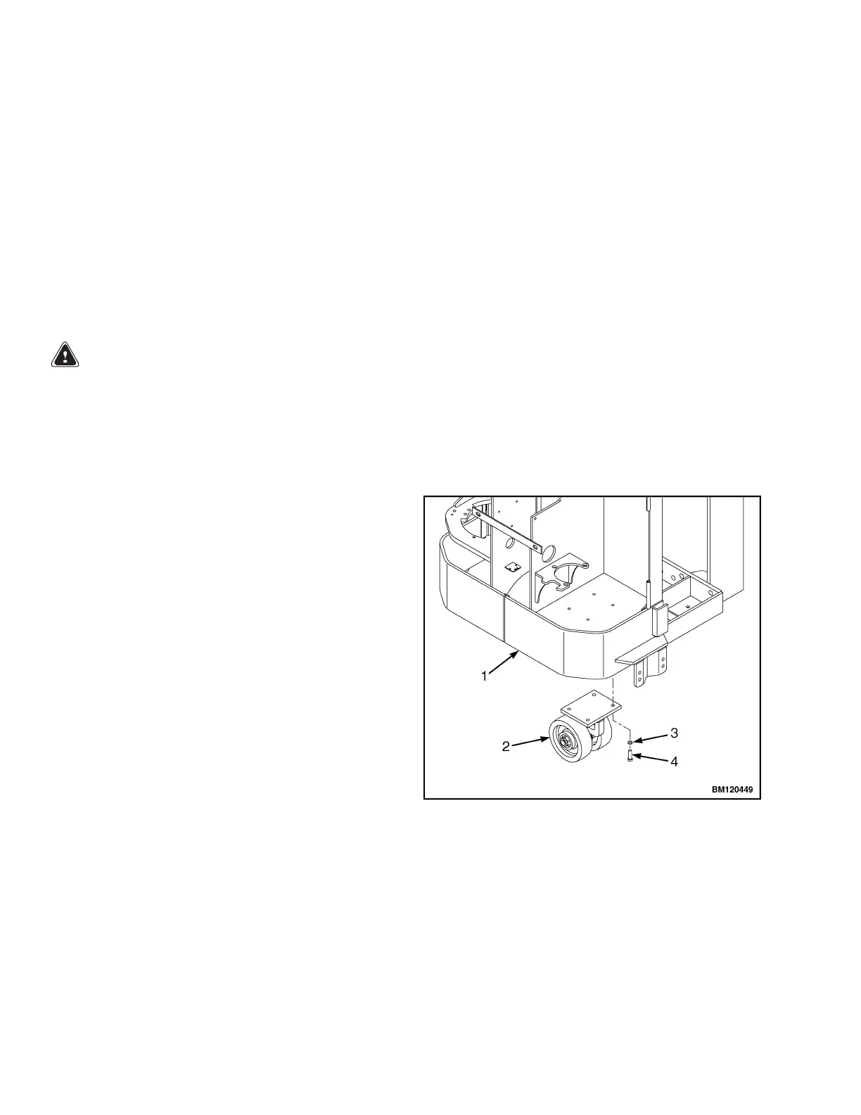
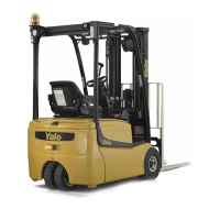
CASTER A
ND CASTER WHEELS
Descrip
tion
The cast
er is one support for the front of the lift truck
and is un
der the hydraulic compartment. See Figure 2.
The drive wheel of the master drive unit is the other sup-
port for this end of the lift truck. The axle of the caster
is an articulated axle. The articulated axle permits both
wheels of the caster to always have equal weight. This
allows for better operation and wear. The caster is fas-
tened to the frame weldment by four capscrews and
lockwashers. The complete caster can be replaced as a
unit, or the wheels can be replaced. Always replace the
wheels as a set for better caster operation and wheel
wear. A single new wheel of the set will wear rapidly.
1. FRAME WELDMENT
2. CASTER ASSEMBLY
3. LOCKWASHER
4. CAPSCREW
Figure 2. Caster (SS030BE and SS030BF)
2