16
O1X
4. AN Circuit Board
(Time required : About 5 minutes.)
4-1. Pull out the nine (9) knobs and the nine (9) VR knob
bushings from the control panel. (Fig. 1)
4-2. Remove the side panel L and R. (See procedure 1)
4-3. Remove the bottom cover. (See procedure 2)
4-4. Remove the DM circuit board and MLN2 circuit board.
(See procedure 3)
4-5. Remove the three (3) screws marked [102]. The DM
shield plate can then be removed. (Fig. 2)
4-6. Remove the three (3) screws marked [63]. The three (3)
contacts can then be removed. (Fig. 3)
4-7. Remove the ten (10) screws marked [62]. The AN circuit
board can then be removed. (Fig. 3)
* When installing the AN circuit board, tighten the screws
"1 and 2" of those marked [62] of the rear panel first.
4-8. Pull out the nine (9) knob spacers from the AN circuit
board.
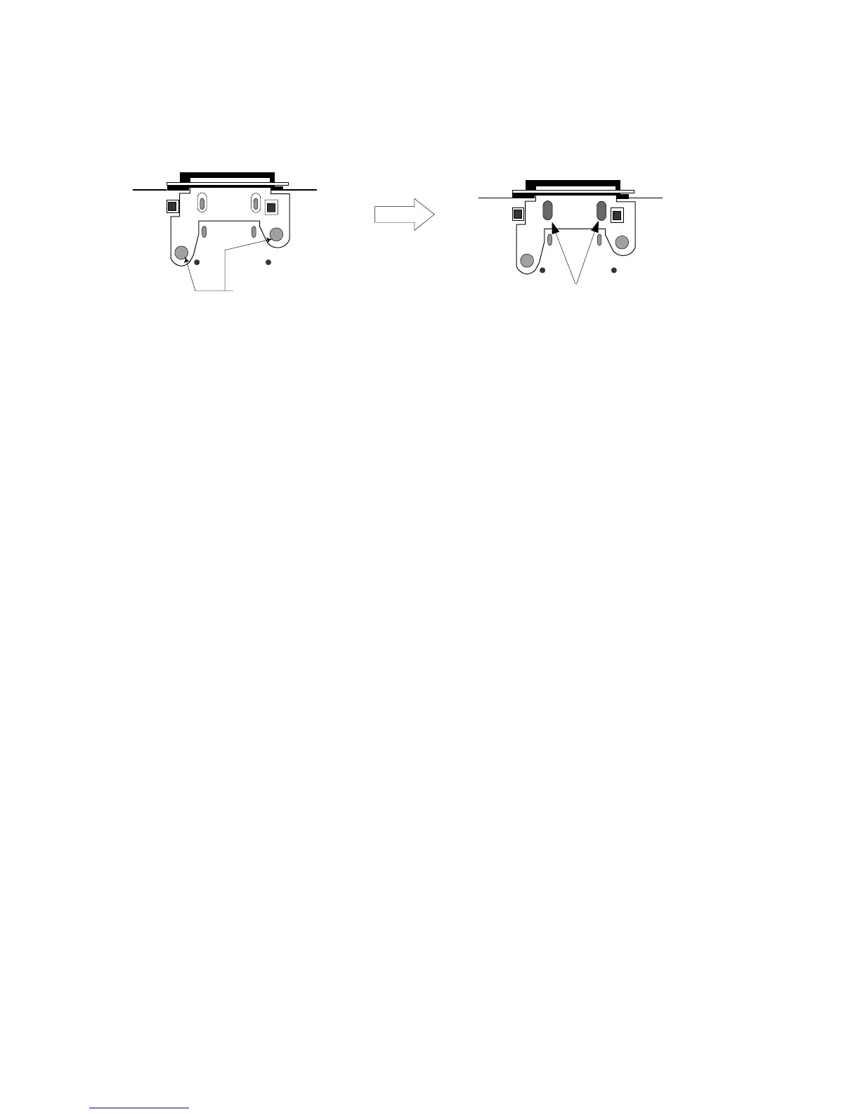
c. 接触子を[60]のネジ2本で基板に固定します。(Fig.2-4)
d. 2箇所に手盛り半田をします。(Fig.2-4)
この時、接触子が浮かないように注意してください。
Patternside
(パターン側)
[60]
+
+
+
+
2points/2箇所
(Fig. 2-4)
[60]: Bind Head Tapping Screw-P 2.0 x 6 MFZN2BL (VG893800)
+バインドPタイト
c. Fix the contact to the circuit board with 2 screws marked
[60]. (Fig. 2-4)
d.
Fix the contact with manual soldering at 2 points. (Fig. 2-4)
Use special care so that the contact is fixed securely.
4. ANシート (所要時間:約5分)
4-1. コントロールパネルからノブ(上)極小を9個、VRブッ
シュを9個、抜き取ります。(Fig.1)
4-2. サイドパネルL、Rを外します。(1項参照)
4-3. ボトムカバーを外します。(2項参照)
4-4. DM、MLN2シートを外します。(3項参照)
4-5. [102]のネジ3本を外し、DMシールドを外します。
(Fig.2)
4-6. [63]のネジ3本を外し、接触子を3個外します。(Fig.3)
4-7. [62]のネジ10本を外し、ANシートを外します。(Fig.3)
※ ANシートの取り付けの際は、リア面の[62]ネジ1→2を先に
締めます。
4-8. ANシートからノブスペーサを9個抜き取ります。
5. MFシート (所要時間:約3分)
5-1. コントロールパネルからスライダーノブを9個抜き取
ります。(Fig.1)
5-2. サイドパネルL、Rを外します。(1項参照)
5-3. ボトムカバーを外します。(2項参照)
5-4. [74]のネジ9本を外し、MFシートを外します。(Fig.4)
※ MFシートの取り付けの際は、[74]ネジ1→2を先に締めま
す。
※ MFシート(フェーダー)を交換後は、フェーダーのキャリブ
レーションを実施してください。(63ページ参照)
5. MF Circuit Board
(Time required : About 3 min.)
5-1. Pull out the nine (9) slider knobs from the control panel.
(Fig. 1)
5-2. Remove the side panel L and R. (See procedure 1)
5-3. Remove the bottom cover. (See procedure 2)
5-4. Remove the nine (9) screws marked [74]. The MF circuit
board can then be removed. (Fig. 4)
* When installing the MF circuit board, tighten the screws
"1 and 2" of those marked [74] of the bottom cover first.
* After replacing the circuit board or fader of MF, please
calibrate the faders. (See page 58.)