18
O1X
5-5. MF Support (A, B)
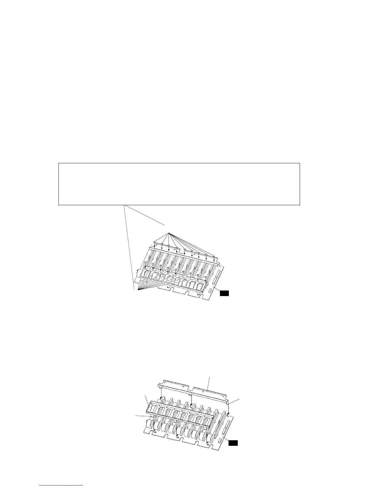
5-5-1. Remove the eighteen (18) screws marked [1]. (Fig. 4-1)
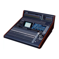
5-5-2. As shown in Fig. 4-2, remove the MF supports (A, B)
from the MF circuit board by sliding the supports toward
outside of the circuit board.
* Don't bend the hooks of the MF supports (A, B) to prevent
distortion.
* When installing the MF supports (A, B), be careful not to
tighten the screw [1] excessively. Overtightening it may
cause the motor fader to malfunction such as unsmooth
movement.
(Fig. 4-1)
(Fig. 4-2)
[1]: Bind Head Screw 3.0 x 4 MFZN2Y (EG330020)
+バインドSタイト
[1]
[1]
MF
MF
MF support A
(MF サポート A)
Hook
(ツメ
Hook
(ツメ)
MF support B
(MF サポート B)
Tightening torque 0.25N•m or less
<Reference>
Matsushita EZ6220 Electric Screwdriver
Clutch : 1 Speed : Low
0.2 to 0.23N•m
締め付けトルク 0.25N・m以下
<参考>
松下EZ6220電動ドライバー
クラッチ:1 速度:Low
0.2〜0.23N・m
5-5.
MFサポート(A,B)
5-5-1. [1]のネジ18本を外します。(Fig.4-1)
5-5-2. Fig.4-2のようにMFサポート(A,B)を基板の外側に向
かってスライドさせ、MFシートからMFサポート(A,
B)を外します。
※ MFサポート(A,B)のツメは歪み防止のため曲げないでくだ
さい。
※ MFサポート(A,B)の取り付け時は、[1]のネジを強く締めす
ぎるとモーターフェーダーがスムーズに動かないなどの不
具合が発生することがあります。