20
O1X
8. RE Circuit Board
(Time required : About 6 min.)
8-1. Pull out the eight (8) encoder knobs from the control
panel. (Fig. 1)
8-2. Remove the side panel L and R. (See procedure 1)
8-3. Remove the bottom cover. (See procedure 2)
8-4. Remove the DM circuit board and MLN2 circuit board.
(See procedure 3)
8-5. Remove the AN circuit board. (See procedure 4)
8-6. Remove the three (3) screws marked [52A]. The AN
support angle can then be removed. (Fig. 3)
* When installing the AN support angle, tighten the screws
"1 and 2" of those marked [52A] first.
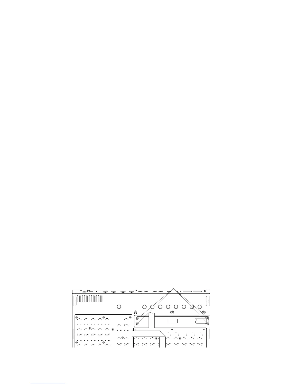
8-7. Remove the three (3) screws marked [26]. The LCD
shield plate can then be removed. (Fig. 5)
* When installing the LCD shield plate, tighten the screws
"1 and 2" of those marked [26] first.
8-8. Remove the five (5) screws marked [52B]. The RE circuit
board can then be removed. (Fig. 5)
* When installing the RE circuit board, tighten the screws
"1 and 2" of those marked [52B] first.
8. REシート (所要時間:約6分)
8-1. コントロールパネルからエンコーダーノブを8個抜き
取ります。(Fig.1)
8-2. サイドパネルL、Rを外します。(1項参照)
8-3. ボトムカバーを外します。(2項参照)
8-4. DM、MLN2シートを外します。(3項参照)
8-5. ANシートを外します。(4項参照)
8-6. [52A]のネジ3本を外し、ANサポートアングルを外しま
す。(Fig.3)
※ ANサポートアングルの取り付けの際は、[52A]ネジ1→2を
先に締めます。
8-7. [26]のネジ3本を外し、LCDシールド板を外します。
(Fig.5)
※ LCDシールド板の取り付けの際は、[26]ネジ1→2を先に締
めます。
8-8. [52B]のネジ5本を外し、REシートを外します。(Fig.5)
※ REシートの取り付けの際は、[52B]ネジ1→2を先に締めま
す。
9. LCD (Time required : About 6 min.)
9-1. Remove the side panel L and R. (See procedure 1)
9-2. Remove the bottom cover. (See procedure 2)
9-3. Remove the DM circuit board and MLN2 circuit board.
(See procedure 3)
9-4. Remove the AN circuit board. (See procedure 4)
9-5. Remove the three (3) screws marked [52A]. The AN
support angle can then be removed. (Fig. 3)
* When installing the AN support angle, tighten the screws
"1 and 2" of those marked [52A] first.
9-6. Remove the three (3) screws marked [26]. The LCD
shield plate can then be removed. (Fig. 5)
* When installing the LCD shield plate, tighten the screws
"1 and 2" of those marked [26] first.
9-7. Remove the four (4) screws marked [22]. The LCD can
then be removed. (Fig. 6)
9. 液晶ディスプレイ (所要時間:約6分)
9-1. サイドパネルL、Rを外します。(1項参照)
9-2. ボトムカバーを外します。(2項参照)
9-3. DM、MLN2シートを外します。(3項参照)
9-4. ANシートを外します。(4項参照)
9-5. [52A]のネジ3本を外し、ANサポートアングルを外しま
す。(Fig.3)
※ ANサポートアングルの取り付けの際は、[52A]ネジ1→2を
先に締めます。
9-6. [26]のネジ3本を外し、LCDシールド板を外します。
(Fig.5)
※ LCDシールド板の取り付けの際は、[26]ネジ1→2を先に締
めます。
9-7. [22]のネジ4本を外し、液晶ディスプレイを外します。
(Fig.6)
[22]: Bind Head Tapping Screw-B 3.0 x 6 MFZN2Y (EP600130) +バインドBタイト
(Fig. 6)
LCD
[22]