2-1
E
EMU01206
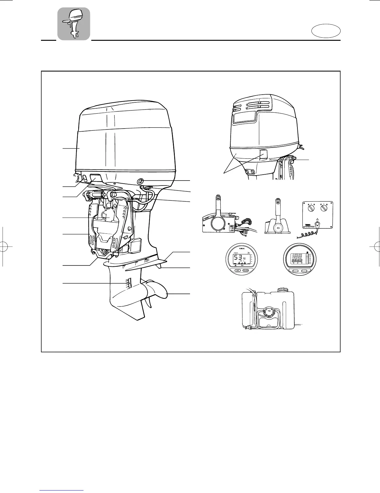
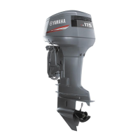
MAIN COMPONENTS
q
e
r
t
y
u
i
o
!1
!2
!3
TRIP TIME BATT
Km/h
knot
mph
km
mile
SPEED
YAMAHA
set
mode
!5
!8
@0
!0
w
!9
!1
!4
!6 !7
1 Power trim and tilt switch
* 2 Flushing device
3 Tilt support lever
4 Anti-cavitation plate
5 Trim tab (Anode)
* 6 Propeller
7 Cooling water inlet
8 Anode
9 Clamp bracket
0 Power trim and tilt unit
q Cowling release lever*1/
Cowling lock lever*2
w Choke knob
e Top cowling
r Cooling water pilot hole
* t Remote control box (Side mount type)
* y Remote control box
(Binnacle mount type)
* u Switch panel (For use withy)
* i Digital tachometer
* o Digital speedmeter
* p Remote oil tank
*1.V4
*2.V6
* May not be exactly as shown; also may not
be included as standard equipment on all
models.
64C-9-16-2 4/18/01 11:30 AM Page 20