14
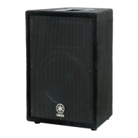
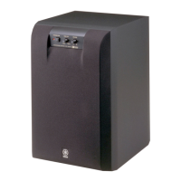
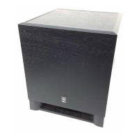
SPEAKER SYSTEM/SUBWOOFER
A10/A12/A12M/A15/A15W
Photo.9
[38]: Nut (ES200030)
Photo.8
Photo.10
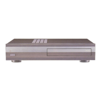
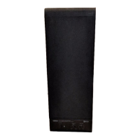
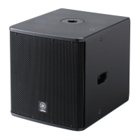
6. Terminal Plate, Network
(Time required: About 2 minutes)
6-1 Remove the four (4) screws marked [12B]. The
network and terminal plate can then be removed.
(Photo.8)
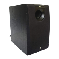
6-2 Network
6-2-1 Remove the four (4) screws marked [33]. The
network can then be removed. (Photo.9)
[12]: +Bind Head Tapping Screw D4.0/L25 Black (AAX59670)
[39]: +Flat Head Machine Screw M3.0/L12 Black (V5993400)
Terminal Plate
Neutrik NL4MP
(With Hexagonal nut)
[12B]
[39]
[12B]
Phone Jack
[38]
Phone Jack
[33]
Network
Terminal Plate
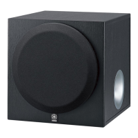
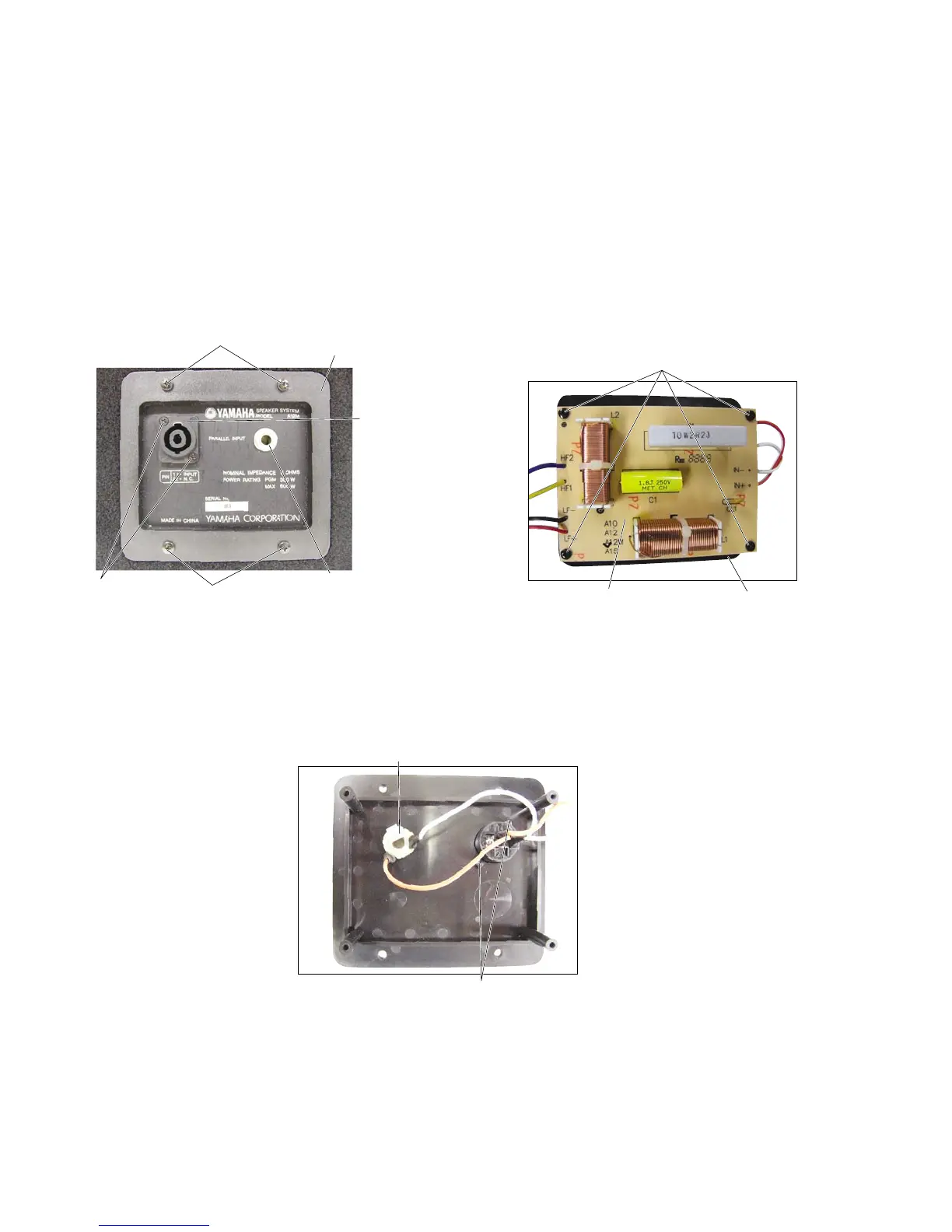
6-3 Remove the two (2) screws marked [39] and the two
(2) hexagonal nuts marked [38]. The neutrik NL4MP
can then be removed. (Photo.8, 10)
6-4 Remove the hexagonal nut. The phone jack can then
be removed. (Photo.8, 10)
[33]: +Bind Head Tapping Screw D3.0/L20 Black (VI064700)
 Loading...