9
SPEAKER SYSTEM/SUBWOOFER
A10/A12/A12M/A15/A15W
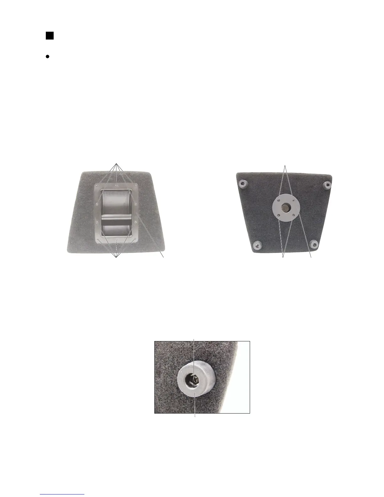
Photo.1
[5]: +Bind Head Tapping Screw D4.0/L16 Black (AAX59650)
Photo.3
Photo.2
[42]: +Bind Head Wood Screw D5.0/L30 (AAX59870)
(A10)
[5A]
[5A]
Metal handle
[26]
[26]
Tripod Support Mount
[26]: +Flat Head Tapping Screw D5.0/l25 Black (AAX59770)
[42]
Rubber foot
DISASSEMBLY PROCEDURE
A10/A12/A15
1. Metal Handle
(Time required: About 2 minute)
1-1 Remove the ten (10) screws marked [5A]. The metal
handle then removed. (Photo. 1)
2. Tripod Support Mount
(Time required: About 1 minutes)
2-1 Remove the four (4) screws marked [26]. The tripod
support mount can then be removed. (Photo.2)
3. Rubber Foot (Time required: About 1 minutes)
3-1 Remove the screw marked [42]. The rubber foot can
then be removed. (Photo.3)