18
● Using the Footswitches and Bank
Switch
• Press a Footswitch (1-3) to select the corre-
sponding patch number 1-3 in the currently se-
lected bank.
* If the Footswitch’s function is set to “EFF” in the Utility
Mode, it will not be possible to directly select a patch with
the Footswitch. (→ page 24)
• Press and hold the BANK switch until the dis-
play and the footswitch lamp flashes (Bank Se-
lect Mode), then remove your foot from the
switch. In this condition, the following procedure
can be used.
* Even when the Footswitch function is set to “EFF” in the
Utility Mode, stepping on the BANK switch will enter this
mode.
1. Press Footswitch 1 to switch between the USER
AREA (U) ↔ PRESET AREA (P). Changing to
another area will cause the Footswitch’s lamps
to flash.
2. Each time Footswitch 2 is pressed, the Bank
Number will decrease by 1.
3. Each time Footswitch 3 is pressed, the Bank
Number will increase by 1.
4. [If the Footswitch Function is set to “PrG”]
Press the BANK switch to return to the Play
Mode. The patch number that was selected be-
fore performing step 1 of this procedure will be
selected.
[If the Footswitch Function is set to “EFF”]
Press the BANK switch and the patch number in
the display will flash. Footswitches 1-3 can be
used to select their corresponding patches (1-
3).
Press the BANK switch to return to the PLAY
Mode with the Area/Bank/Patch you just selected
ready.
* To cancel the Area/Bank/Patch you just selected, press the
BANK switch. The AG-Stomp will return to its previous con-
dition.
Using the AG-Stomp
● Using a MIDI Controller
Patches in the AG-Stomp can also be selected by
transmitting MIDI Program Change data from an ex-
ternal MIDI device such as the YAMAHA MIDI Foot
Controller MFC10, etc.
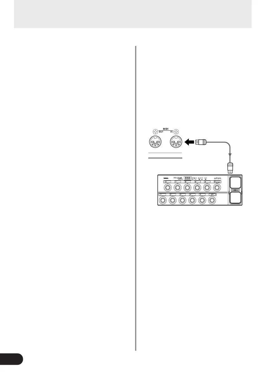
1. Connect the MIDI IN jack on the AG-Stomp to
the MIDI OUT jack on an external MIDI device
with a MIDI cable.
* Make sure a standard MIDI cable is used. Also, the length
of the MIDI cable should be limited to 15 meters. The use
of a longer cable may result in trouble such as inferior per-
formance of the device, etc.
2. Match the AG-Stomp’s MIDI receive channel,
with the MIDI transmit channel on the external
MIDI device.
→ page 25 [Set the MIDI Receive Channel]
3. Create a Program Change Table*.
→ page 24 [Create a Program Change Table]
* This operation assigns patch numbers to corresponding
program change numbers that are received from an exter-
nal device. For example, when the program change num-
ber “1” is received, the AG-Stomp’s patch number “U13”
is recalled.
* The default for Program Change Number: Patch Number
is
1: U01, 2: U02, ... 60: P93, 61: U01, ... 120: P93, ...128: U22.
4. When program change data is transmitted from
an external MIDI device and received by the AG-
Stomp, the corresponding patch in the Program
Change Table you created will be selected.
* Refer to the Owner’s Manual of your external MIDI de-
vice, etc., for information on how to transmit program
change data.
MIDI IN
MIDI
OUT
MFC10, etc