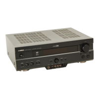
Do you have a question about the Yamaha DSP-A2 and is the answer not in the manual?
Frequency Response | 20Hz - 20kHz |
---|---|
Total Harmonic Distortion | 0.015% |
Type | AV Amplifier |
Input Sensitivity | 200 mV (Line) |
Channel Separation | 60 dB |
Speaker Load Impedance | 4-16 ohms |
Video Connections | Composite, S-Video |
Surround Sound Formats | Dolby Digital, DTS |
Signal-to-Noise Ratio | 100 dB |
Dimensions | 435 x 171 x 476 mm |
Damping Factor | 80 (8 ohms, 1kHz) |
Digital Inputs | 2 Coaxial |
DSP Modes | Cinema DSP |
Inputs | Phono |
Outputs | Speaker Outputs |
Information on critical components requiring exact replacement with specified parts.
Safety warnings regarding impedance selector usage and static discharge prevention.
Rear panel connection layouts for R, T, B, and G models.
Minimum, maximum, and dynamic output power per channel.
Tone control, filters, separation, and RIAA equalization.
Power supply, consumption, dimensions, and weight.
Table of DSP programs with delay, room size, and other parameters.
Settings for speaker configuration and digital audio formats.
Settings for delay, initialization, memory guard, input, and dimmer.
Settings related to superimposing display signals.
Diagram showing internal components with reference numbers.
Steps for removing top cover, bottom cover, and front panel.
Procedure to start diagnosis and how the menu is displayed.
Explanation of I PROTECTION, PS PRT, DC PRT, TMP PRT errors.
Information on how protection history is stored and cleared.
Procedure to cancel DIAG and navigate menus.
Functions available and initial settings for DIAG.
Details of the analog through diagnostic mode.
Details of the DSP through diagnostic modes.
Details of the DSP full bit diagnostic mode.
Details of the AC3/DTS throughput diagnostic mode.
Details of the Pro Logic diagnostic mode.
Details of the speaker settings menu.
Diagnostic check for the FL display section.
Diagnostic test using noise generator.
Menu for managing preset data and initialization.
Diagnostic check for A/D conversion values.
Displays status data from the sub-microprocessor.
Checks DSP microprocessor checksum and software version.
Procedure to confirm idling current and test points.
Pin details for IC3 (HD64F3337YF16).
Pin details for IC14 (LC87F5164).
Pin details for IC4 (YSS918).
Pin details for IC10 (PM4007A).
Pin details for IC3 (YM3436DK).
Pin details for IC611 (LC74781-9626).
Layout of grid segments and pattern area for display data.
Pinout diagrams for integrated circuits and transistors.
Pinout diagrams for diodes.
PCB layouts for DSP, Digital In, and Function boards.
PCB layouts for Video, Operation, and Main boards.
Two-part overall block diagram illustrating signal flow.
Circuit schematics for Function boards.
Circuit schematic for the Digital In section.
Circuit schematic for the DSP section.
Circuit schematics for Video boards.
Circuit schematics for Operation boards.
Circuit schematics for Main boards.
List of electrical components with part numbers and descriptions.
List of carbon resistors with values and part numbers.
List of chip resistors with values and part numbers.
Exploded view of the remote control transmitter.
Circuit schematic for the remote control transmitter.
Diagram of key layout and table of fixed codes.
Explanation of learning, macro, and key action functions.
Information on key lighting, control transmission, and macro transmission.