Do you have a question about the Yamaha B-2 and is the answer not in the manual?
Details the circuit board for the selector switch.
Describes the circuit board for the pin jack inputs.
Details the circuit board for the amplifier's drive stage.
Outlines the power supply circuit board.
Details the circuit board for volume control.
Shows the connector board for power FETs.
Describes the circuit board for meters and lamps.
Details the circuit board for LEDs.
Details the technical specifications for the power amplifier.
Outlines specifications for the peak meter functionality.
Lists general specifications not covered elsewhere.
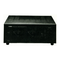
Identifies components on the front of the unit.
Locates components on the rear of the unit.
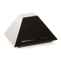
Illustrates the layout of components from the top.
Shows the arrangement of components from the bottom.
Explains the initial stage circuit design.
Describes the second stage differential amplifier.
Details the unit's protective mechanisms.
Explains the automatic bias adjustment system.
Describes the push-pull driver circuit.
Details the circuit that protects speakers.
Explains the input connection options.
Instructions for removing the top panel.
Steps to remove the bottom panel.
Guide to remove the power supply board.
Instructions for removing the power FET unit.
Steps to remove the drive circuit board.
Guide to remove the power supply transformer.
Instructions for removing the electrolytic capacitor board.
Steps to remove the pin jack circuit board.
Guide to remove meter/lamp boards.
Instructions for removing the front panel.
Steps to remove the LED circuit board.
Guide to remove the power switch.
Instructions for removing the peak level meter.
Steps to remove the selector switch board.
Guide to remove the volume circuit board.
Essential steps before making adjustments.
General procedures for initial adjustments.
Steps to adjust power supply voltages.
Procedures for adjusting the main amplifier.
Steps to adjust the meter amplifier section.
Diagram of the pin jack circuit board.
Diagram of the drive circuit board.
Diagram of the volume circuit board.
Diagram of the connector circuit board.
Diagram of the power FET circuit board.
Diagram of the meter amp circuit board.
Diagrams for power supply boards.
Diagram of the lamp circuit board.
Diagram of the electrolytic capacitor board.
| Type | Power Amplifier |
|---|---|
| Frequency Response | 5Hz - 100kHz (±0.5dB) |
| Input Sensitivity | 0.775V |
| Signal-to-Noise Ratio | 100 dB |
| Dimensions | 430 x 170 x 430mm (W x H x D) |
| Weight | 12 kg |
| Damping factor | 100 |
| Total Harmonic Distortion | 0.005% |
| Speaker load impedance | 4Ω - 16Ω |
| Power Output | 100 watts per channel into 8Ω (stereo) |